How to Build a Smartphone USB Based Controller Systems
with a smartphone (or tablet) with USB-OTG (USB - On The Go) support
also known as an Android device that supports USB-Host mode
If you want to build your own control system, you can review some options at
Control Systems.
The option described here, to build your own controller device, is that you could leverage an Android device, USB-OTG port, and USB parallel printer adapter.
For that option, first lets cover some background on the approach, and then the steps to take to build this controller.
The USB interface is directional with one host that can communicate with a number of connected accessories.
The connector on many smartphones only allow them to be an accessory.
This allows the smartphones to be charged or connected to a personal computer to sync data such as photos.
However, some smartphones, such as the Android Samsung S# series, allow an adapter to be plugged in
that then allows USB accessories to be plugged in directly to the smartphone as a host.
An example of this would be to plug in a USB memory stick to an Android smartphone with USB-OTG which then
allows the user to use the Android File Manager to look at or move files to the USB memory stick.
With a smartphone with USB-OTG support and an adapter,
you can connect a USB to parallel port cable.
Parallel ports were designed for early dot matrix printers.
Early dot matrix printers had a print head consisting of a row of seven to nine metal pins connected to solenoids.
When power was applied to the solenoids, the pin was pulled forward to strike the paper and leave a dot.
The parallel port was designed to make it simple to set or clear these pins.
However, instead of a printer head,
a parallel port could control any number of other items like
turning on an electric motor for a wheel on a robot or
switching on or off a control valve for a thruster on a spacecraft.
If you want to use the parallel ports data bits to control items like an LED light or an electric motor,
depending on your parallel port, you will probably need electronics that respond like an older printer.
Otherwise you'll only be able to send one byte,
which will cause the computer to think that the printer is busy and it won't send any more bytes of data.
The parallel or centronics port handshake uses the following pattern.
First, data is presented on the parallel port pins 2 to 9 representing data bits 0 through 7.
The computer then lowers the Strobe line (pin 1), waits a minimum of 1 μS, and then raises the Strobe line.
The data bits would normally be read by the printer on the rising edge of the Strobe line.
The printer electronics would indicate that it is busy processing the data by raising the Busy line (pin 11).
The computer then checks to see if the printer electronics are indicating it is busy, and waits for the Busy line to go low.
Once the printer has accepted data, it will acknowledge receiving the data by a low pulse, about 5 μS, on the Ack line (pin 10).
Quite often the computer will ignore the Ack line to save time, but it won't ignore the Busy line.
Thus, depending on the parallel port hardware or cable you have, any electronics you wire up may need to respond as printer electronics would.
Your electronics might not need to do anything.
They might need to keep the Busy line (pin 11) low so the computer sees that it can keep sending data.
Alternately they might need to raise the Busy line and then lower it to indicate the data has been accepted.
In rare cases your electronics might need to both raise and lower the Busy line and also lower and raise the Ack line (pin 10).
Other parallel port input pins like the Paper-Out line (pin 12), Select line (pin 13), and Error line (pin 15) should be kept low.
Parallel port pins
| Pin (DB25) |
Pin (36 pin) |
Signal Name |
Direction |
| 1 |
1 |
Strobe |
Out Control |
| 2 |
2 |
D0 |
Out Data |
| 3 |
3 |
D1 |
Out Data |
| 4 |
4 |
D2 |
Out Data |
| 5 |
5 |
D3 |
Out Data |
| 6 |
6 |
D4 |
Out Data |
| 7 |
7 |
D5 |
Out Data |
| 8 |
8 |
D6 |
Out Data |
| 9 |
9 |
D7 |
Out Data |
| 10 |
10 |
Ack |
In Status |
| 11 |
11 |
Busy |
In Status |
| 12 |
12 |
Paper-Out |
In Status |
| 13 |
13 |
Select |
In Status |
| 14 |
14 |
Linefeed |
Out Control |
| 15 |
32 |
Error |
In Status |
| 16 |
31 |
Reset |
Out Control |
| 17 |
36 |
Select-Printer |
Out Control |
| 18-25 |
16,17,19-30,33 |
Ground |
Gnd |
How To:
1) collect items you will need
2) identify if your device supports USB-OTG or find a device that does
For this to work you need both your operating system (OS) and hardware to support USB-OTG.
USB host mode is directly supported in Android 3.1 (API level 12) and newer platforms.
Windows Embedded Compact is reported to support USB OTG as of Windows Embedded CE 6.0.
Windows 10 introduces support for USB Dual Role or OTG connectivity.
However, the app we're suppling is only for Android 4.0 or later.
Determining which smartphone hardware supports USB-OTG or USB host is a little hard because
you have to have a USB device attached to the Android device in order for the software to determine if USB-OTG is supported.
To check your hardware, download the Android USB-Controller app to your Android smartphone that you think has USB-OTG support.
Link to USB-Controller  for Android smartphones
Then plug in a USB-OTG adapter to the smartphones USB port and a USB to parallel port cable to that adapter.
Run USB-Controller and select the USB Host Check.
This will tell you what USB devices were identified as being connected to your Android device, or it won't recognize any devices.
If the later occurs, then your Android device doesn't support USB-OTG (aka USB-Host).
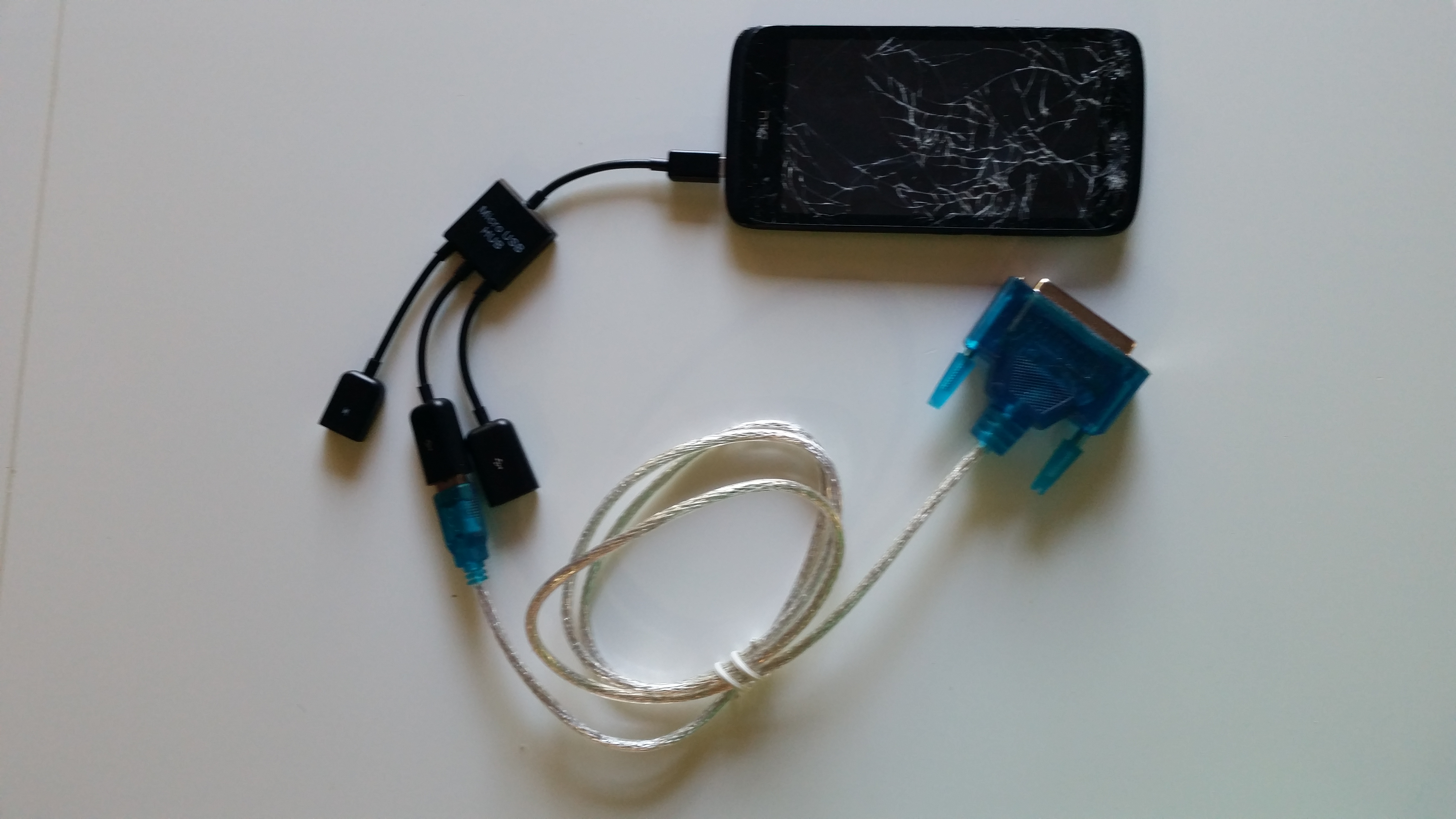
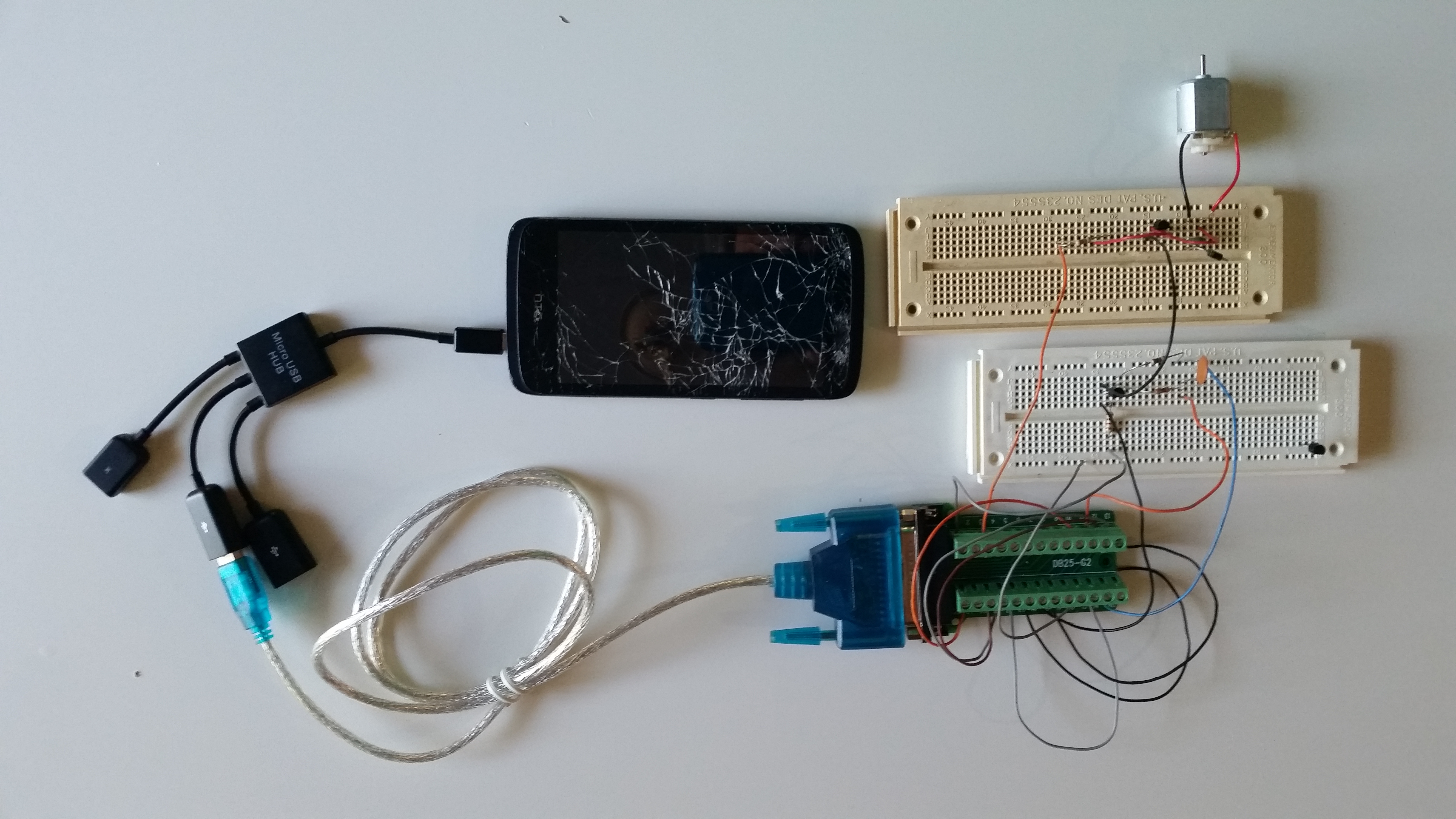
Smartphone connected through a USB-OTG hub to a USB to Parallel port cable
I've confirmed that Samsung Galaxy S5, S6, and S7 support USB-OTG.
The list of devices that should support USB-OTG includes (but is not limited to):
- HTC 10

- HTC One M8
- HTC Butterfly
- HTC Butterfly S
- HTC Desire (A8181)
- HTC Desire VC T328d
- HTC One Dual
- HTC One Mini
- HTC One Mini 2
- HTC J (Z321e)
- HTC One Max
- HTC One X
- Motorola Moto G
- Motorola Moto G4
- Motorola Xoom
- Motorola Droid Razr HD (XT926)
- Samsung Galaxy Alpha
- Samsung Galaxy Note 3
- Samsung Galaxy Note 8.0
- Samsung Galaxy Note (GT-N7000)
- Samsung Galaxy Note II (GT-N7100)
- Samsung Galaxy Note III (GT-N900)
- Samsung Galaxy Note IIII (SM-N910H)
- Samsung Galaxy Note 10.1 (2014 Edition)
- Samsung Galaxy R (GT-I9103)
- Samsung Galaxy J
- Samsung Galaxy S2
- Samsung Galaxy S2 Plus
- Samsung Galaxy S3
- Samsung Galaxy S4
- Samsung Galaxy S5
- Samsung Galaxy S6
- Samsung Galaxy S6 edge
- Samsung Galaxy S7
- Samsung Galaxy S7 edge
- Samsung Galaxy Tab
- Samsung Galaxy Tab Pro 8.4
- Samsung Galaxy Tab Pro 10.1
- Samsung Galaxy Tab 3 8.0 (SM-T310)
- Samsung Galaxy Tab 4 10.1 (SM-T530NU)
- Samsung Galaxy Mega 6.3 (GT-I9200)
- Samsung Galaxy Mega 6.3 (GT-I9205)
- Samsung Galaxy Ace
- Samsung Galaxy Ace 2
- Samsung Galaxy Ace 3
- Samsung Galaxy A7
- Sony Ericsson Xperia Active
- Sony Ericsson Xperia S
- Sony SGPT111JP/S
- Sony SGPT112TW/S
- Sony SGPT211JP/S
- Sony Xperia AX (SO-01E)
- Sony Xperia ACRO S (LT26W)
- Sony Xperia T (LT30P)
- Sony Xperia TX LT29i
- Sony Xperia Z2a
- Sony Xperia Z (C6602)
- Sony Xperia Z ULTRA (C6802)
- Sony Xperia ZL (C6502)
- Sony Xperia ZR (C5502)
- Sony Xperia Z5
- Sony Xperia U (ST25i)
- Acer ICONIA A1-810
- Acer ICONIA Tab A700
- Asus MeMO Pad 10 ME102
- Asus MeMO Pad ME172V
- Asus MeMO Pad ME301T
- Asus MeMO Pad ME302
- Asus MeMO Pad 8 (ME180A)
- Asus MeMO Pad 10 (ME180A)
- Asus MeMO Pad FHD 10 LTE
- Asus MeMO Pad FHD 10
- Asus Transformer Pad TF700T
- Asus Transformer Pad 701T
- Asus Transformer Pad TF-100
- Asus Nexus 7
- Asus PadFone
- Asus PadFone 2
- Asus PadFone Infinity
- BlackBerry Z30
- BlackBerry Passport
- BlackBerry Q20 Classic
- LG G4
- LG LS995 flex
- LG Nexus 5
- LG Optimus G Pro
- LG Optimus G Pro lite
- LG G2 (D800)
- LG G2 (D802)
If you have confirmed that other smartphones or tablets support (or is on this list and doesn't support) USB-OTG
please email us at the teraKUHN project so we can update the list for others.
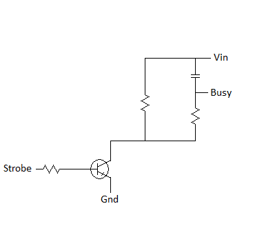
3) build the Strobe to Busy circuit to respond as the parallel or centronics port handshake
As mentioned above, any electronics you wire up may need to respond as printer electronics would.
The most common handshake you will need to produce is to raise and lower the Busy line (pin 11) after the Strobe line is lowered and raised indicating data is available.
In order to do this you could just invert the Strobe line and delay it slightly.
This can be done with a transistor circuit to invert the Strobe line signal,
and then an RC (resistor/capacitor) circuit to delay that signal.
The RC circuits output is then fed back into the Busy line.
The RC circuit generates the delay in the signal based on the time constant of it's components.
When an increasing DC voltage is applied to a discharged capacitor, the capacitor charges,
and when the voltage is reduced over a charged capacitor, the capacitor discharges.
This charging and discharging of a capacitors energy is not instant
If a resistor is connected in series with the capacitor forming an RC circuit,
the capacitor will charge or discharge slower through the resistor.
The time constant T of an RC circuit, is measured in terms of T = R x C, in seconds,
where R is the value of the resistor in ohms and C is the value of the capacitor in Farads.
The bigger the combination of R and C in your circuit, the longer the data bits will be held in their state before then next pulse of data bits.
To provide the small amount of current this circuit needs, you can leverage the Linefeed, Reset, or Select-Printer lines which are outputs that should be held high (5v).
Here's a diagram of the circuit you want to wire up.
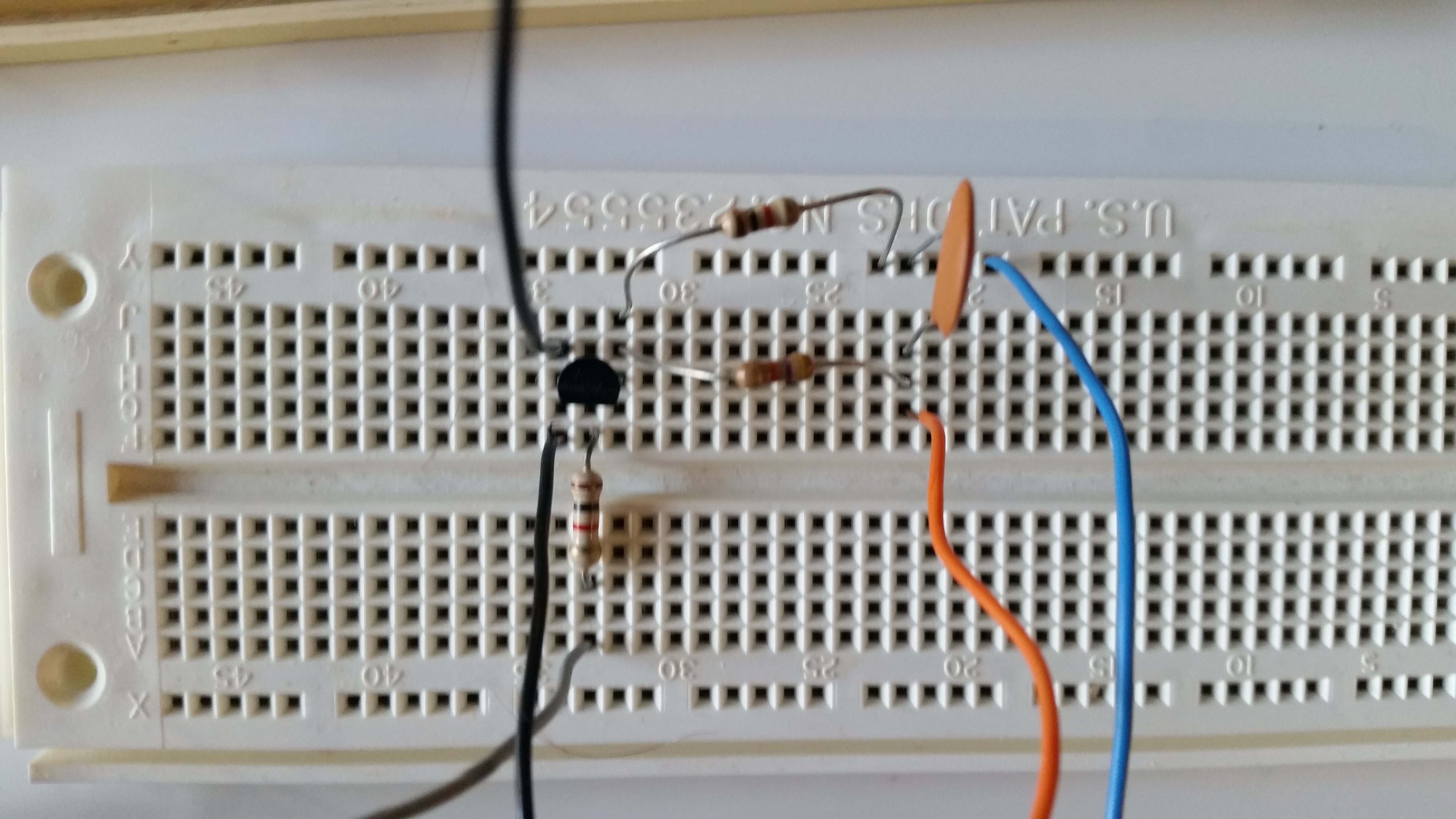
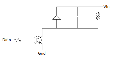
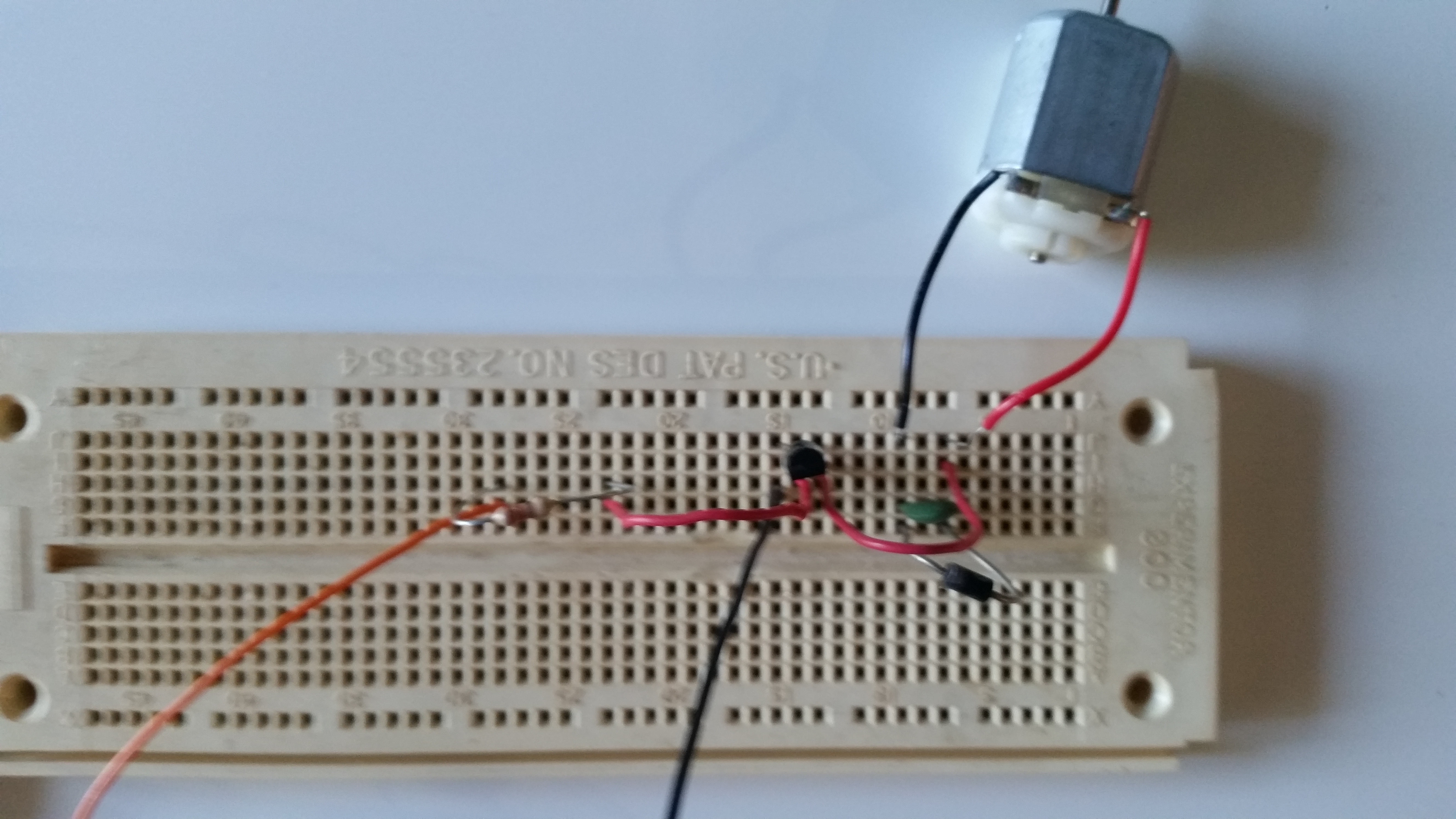
4) Build the simple Motor circuit and wire up a motor or light
You typically shouldn't wire up a digital output directly to a motor since a motor will probably draw more current than the digital output is rated for.
Instead you should have a small amplifying switch circuit, and a separate power supply to drive the motor.
This can be done with a transistor circuit to amplify any of the 8 digital output signals from the parallel port.
A diode and capaciter in parallel to the motor prevents problems with the circuit when the motor is stopped and it momentarily acts as a little generator.
This circuit can be used for driving a small motor from just about any digital output like an Arduino, PC parallel port, etc., not just this project.
Here's a diagram of the circuit you want to wire up.
5) use USB-Controller to control the parallel port
Every time a byte is written to the data ports, the data is only present as long as the Busy line is high.
However, the Strobe to Busy circuit above regularly lowers the Busy line so that you can continue to send control bytes.
Thus you need to continuously send control bytes to the port in order to be able to change the state in the future.
In order to do this, you can use the Android USB-Controller app that you downloaded to your Android smartphone earlier.
Link to USB-Controller for Android smartphones
Set the bits you want to turn on and the select the Send Data button.
The data will be held as long as a pulse count is running.
The pulse count can be set in the USB-Controller apps Settings.
Here's a video of a
Android smartphone (ARM) controlled Snap Rover robot
using this PWM Strobe to Busy circuit and simple Motor circuit and USB-Controller.
Alternatively, instead of using a pulse width modulated (PWM) signal, you could build a digital logic circuit that latches (saves) the data ports triggered by the Strobe line.
You would then connect any motors or lights to the output of these latches.
This might be a better solution for some, but would then require a more complex circuit and a separate power supply for the digital circuit.
You could still use USB-Controller to send the data by using it's Settings to set the pulse count to 1.
Advanced: 6) Build a latch and bi-directional Motor circuit and wire up a motor with an L293 / SN754410 half H-bridge driver
You can't wire up a digital output directly to a motor and be able to control the motor in three different states: stopped, forward, reverse.
Instead you will need two digital outputs, one to control direction and one to turn the motor on and off.
However, the circuits described above for direct motor control rely on PWM and that won't work for this circuit.
Instead you will need to build a latch circuit that saves the state of the data ports between pulses on the Strobe line.
This can be done with a number of latch circuit chips (aka flip-flops) such as the 74LS171, 74LS173, 74LS174, 74LS175 ICs that can handle 4 or more bits.
This example uses a
74LS174,
.
You then need a circuit called an H-bridge in order to be able to switch the current direction to the motor.
This could be built from scratch with transistors, but it's such a popular circuit you can get ICs that have H-bridge or half H-bridge circuits.
The L298 is a popular dual packaged full H-bridge IC, while the L293 (aka SN754410) is a popular quadruple package half H-bridge IC.
You can use two half H-bridge circuits with a little other circuitry to form the equivalent of a full H-bridge so these two ICs offer similar capabilities.
For this example we use an
L293
since it's easier to put this chip into a solderless breadboard.
By using a digital inverter such as a
74LS04,
we can tie two half H-bridges driver inputs together so that one always has the opposite state as the other.
Here's a diagram of the latch and bit-directional motor circuit you want to wire up.
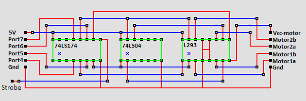
Note that in an h-bridge circuit there is a separate voltage supply for the motors vs. for the digital logic,
similar to the simple motor circuit described above.
With a smartphone, the digital logic voltage can be provided by a modified USB cable.
The motor voltage can be supplied independently and can be different than the 5V supplied for the digital logic.
Also note that with this circuit you will not need the simple motor circuit described above.
However, you will still need the strobe to busy circuit.
To send the data from your smartphone through USB to the parallel port, you can either use USB-Controller (free or Pro) with the pulse count in Settings set to 1 or use AVR-Controller Pro.
Link to USB-Controller for Android smartphones
Link to AVR-Controller  for Android smartphones
Now you need to write a program that sets both a direction bit and a bit to turn on or off the motor,
and call a wait routine.
The data will be held by the latch indefinately, but the program will not advance as long as it is in the wait routine.
Once the wait routine is done, clear the bits and write them to the digital port to turn the motors off before turning them on in a different direction.
Here's an example of the KCC80 KIOS C code that, with the above circuit and USB-Controller Pro, can be used to drive a rover with tank drive.
It should be able to drive the rover forward, then reverse, and then turn before repeating.
For an example of the code that, with the above circuit and AVR-Controller Pro, can be used to drive a rover with tank drive see the code example on
Arduino Controller
.
// determine ROM size and KIOS location based on page zero setting
const int wWarmStartAddr = 1;
extern void locatekios_prnout(char motorPins)
{
_asm ld c, (ix+motorPins@locatekios_prnout)
_asm ld de, 0Ch ;; KIOS +0Fh-3 List {aka PRN Out}
_asm ld hl, ( 1 ) ;; ( wWarmStartAddr )
_asm add hl, de
_asm pop ix
_asm jp (hl)
}
const int nTimePerDistance = 1; // ToDo: implement
const int nTimePerAngle = 1; // ToDo: implement
void SimpleDelay(int nTime)
{
while (nTime > 0)
{
nTime = nTime - 1;
}
}
// stopped
void Stop()
{
locatekios_prnout(0x00);
SimpleDelay(1000);
}
extern void setup()
{
Stop();
}
// forward
void Forward(int nDistance)
{
locatekios_prnout(0x0F);
SimpleDelay(nDistance * nTimePerDistance);
}
// reverse
void Reverse(int nDistance)
{
locatekios_prnout(0x05);
SimpleDelay(nDistance * nTimePerDistance);
}
// forward on one side and reverse on the other
// results in turning
void TurnRight()
{
locatekios_prnout(0x07);
SimpleDelay(5000);
}
extern void loop()
{
Forward(5000);
Stop();
Reverse(5000);
Stop();
TurnRight();
Stop();
}
extern void main()
{
setup();
while (true)
{
loop();
}
}
Keep in mind that USB-Controller (free or Pro) or AVR-Controller Pro work through USB-OTG.
USB has a host/accessory or host/peripheral topology and protocol.
Normally a computer is the host and the accessory may be a USB flash drives, USB mouse, USB keyboard, USB printer port, etc. or even a smartphone or tablet.
USB-OTG allows USB devices, such as smartphones or tablets, to switch from acting as accessory to act as the host, allowing other USB devices, such as USB flash drives, USB mouse, USB keyboards, and USB printer ports to be attached to them.
Here's the catch, when this switch happens, the smartphone or tablet becomes the power supplier of the USB peripherals.
While you can get a USB-OTG host hub that you can plug a USB power supply into, that USB power supply only goes to the USB peripherals, not to the device acting as the host.
USB-Controller and AVR-Controller were meant for mobile robotics projects like:
Android smartphone (ARM) controlled Snap Rover robot
where mobility is more important than duration.
To keep a smartphone powered on longer, you might need something like wireless charging or a power supply that you can plug into the smartphone instead of its battery.
You will not be able to power the smartphone through it's USB port.
If your scenario is one where duration is more important than mobility you should look at
PC based Controller Systems.
It's the same concept as that presented here, but using a PC instead.
On the other hand, you could look at
Arduino based Controller Systems.
Here are some architecture characteristics that can be demonstrated by these two control solutions.
These differences can be used for teaching processor and microcontroller concepts.
control solutions
| Z80 custom with KIOS |
AVR Arduino |
|
CISC
|
RISC
|
|
von Neumann architecture
|
Harvard architectures
|
|
Run-time software abstraction layer
|
Compile time coding abstraction macros
|
|
custom electonics board
|
pre built Arduino board
|
|
|
|
Copyright (C) 2017 - 2026 R. J. Kuhn.
Please note that you are not allowed to reproduce or rehost this page without written permission.