
USB-Controller NoAds is now USB-Controller Pro with a Z80 programming model. Version 1.20 or greater of USB-Controller adds a complete Z80 microcontroller simulator. USB-Controller Pro includes the ability to open *.hex files transferred to your Android smartphone from a PC in addition to saving and restoring 4 program profiles. The embedded Z80 microcontroller simulator allow hobbyists and students to use other PC based development tools to program USB-Controller. What that means is you can write Z80 code on your PC, assemble it into a *.hex file, transfer it to your Android smartphone, open it in Z80 USB-Controller Pro, and run the program. This could enable several programming models beyond Z80 assembly such as Fortran, Pascal, Forth, C, C++, or even visual block programming system on your PC. This also enables more complex program operations than the simple sequence of up to 64 output steps that are supported by the USB-Controller program UI. To get the Z80 code to interact with the USB port supported by USB-Controller you need to have your Z80 code call into the teraKUHN IO subsystem, or KIOS. USB-Controller Z80 code and KIOS calls have a similar layout to older Z80 CP/M operating system BIOS calls. Note that the free version of USB-Controller includes the Z80 simulator, but doesn't support file operations so you can't load your own Z80 code with the free version.
| ROM size | calculation |
|---|---|
| 8K | bias = 8K - 8K = 0K = 0 |
| 12K | bias = 12K - 8K = 4K = 1000h |
| 16K | bias = 16K - 8K = 8K = 2000h |
| 20K | bias = 20K - 8K = 12K = 3000h |
| 24K | bias = 24K - 8K = 16K = 4000h |
| 32K | bias = 32K - 8K = 24K = 6000h |
| 48K | bias = 48K - 8K = 40K = A000h |
| 64K | bias = 64K - 8K = 56K = E000h |
Address references in each step are shown with a trailing 'h' which denotes the hexadecimal number system, and are given for a 8K ROM memory system. For larger ROM systems, add a 'bias' to each address which is shown with a +bias following it, where bias is equal to the ROM memory size - 8K. Values for bias in various standard ROM memory sizes are listed in the table.
Note that the standard distribution version of KIOS in USB-Controller is set for operation within a 32K ROM memory system. Also, if you select the 'Project', 'KIOS/BIOS Stubs' option in Debug Z80 , the stubs will be located for operation of a 32K ROM memory system. The reason you would have smaller or larger systems is if you were to build a physical 8080, 8085, Z80, Z180, eZ80, or Rabbit 2000 based circuit board and configure less or more than 32K of ROM memory on the system. The reason USB-Controller is set for a 32K ROM memory system is that an easy physical system to build would be 32K of ROM and 32K of RAM where all code and read only data variables are located below 8000h and all read/write data variables and program stack are located at or above address 8000h.
As a side note, in addition to KIOS and CP/M which both work on 8085/Z80 processors, the Sojourner Mars Rover also used an 8085 processor. Since the flat 16-bit (64K) address space of the 8085 was insufficient for the data and code requirements of the Sojourner Mars Rover mission, additional memory was provided, along with hardware to map the 64K logical address space into a larger physical memory space. The first 16K of the logical address space (0000h-3FFFh) was mapped into rad hard ROM at startup, then switched to rad hard shadow RAM. It was used for interrupt vectors and handlers, top-level control (the main loop/command dispatcher), and common library functions (compiler support library, device I/O, communications, etc.) The next 16K of the logical address space (4000h-7FFFh) was always mapped to rad hard RAM, and was used primarily for data (e.g. stack, state information, variables, buffers). The last two 16K of logical space were each mapped through bank registers (BANK1 for addresses 8000h-BFFFh, and BANK2 for addresses C000h-FFFFh) into any two of several physical memory segments. By configuring KIOS for a 16K ROM memory system, it would have a similar memory layout to the first two 16K memory banks of the Sojourner Rover.
The entry points into the KIOS are detailed below. Entry to the KIOS is through a 'jump vector' located at 1A00h+bias, as shown below. The jump vector can be a sequence of jump instructions which send program control to the individual KIOS subroutines. KIOS calls try to have a similar layout to older Z80 CP/M BIOS calls. Under USB-Controller KIOS subroutines will by empty for most functions (they will contain a ret instruction). This is because when the Z80 code calls the KIOS routine in USB-Controller, the Z80 simulator turns control over to USB-Controller to handle I/O operations. If you are going to build a physical CPU system, you would change these ret instructions into jp instructions that jump to code you write to handle the hardware you built. The jump vector at 1A00h+bias takes the form shown below, where the individual jump addresses are given to the left:
Each jump address corresponds to a particular subroutine which performs the specific function, as outlined below.
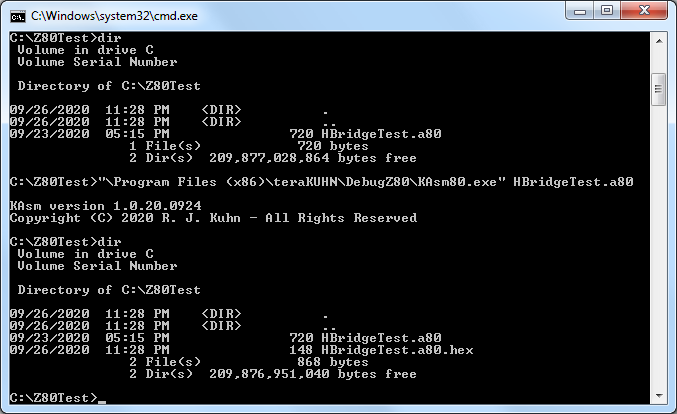
If you want to write a Z80 assembly program on your PC, you can assemble the file with
KAsm80 which comes with Debug Z80  .
.
First you need to write a program. Here's an example of a Z80 assembly program that pulses bits in USB parallel printer port as if it's wired to an H-bridge circuit for turning on and off motors.
ORG 00001h
WarmStartAddr:
ORG 00100h
setup:
;; do any I/O hardware setup operations here
jp loop
;; determine ROM size and KIOS location based on page zero setting
locatekios:
ld hl, (WarmStartAddr)
add hl, de
jp (hl)
;; delay is a constant so it can reside in ROM with program instead of RAM
delay:
DD 32768
loop:
;; forward
ld a, 03Ch ;; output bits 00111100
ld bc, delay
ld de, 00066h
call locatekios
call stop
;; reverse
ld a, 014h ;; output bits 00010100
ld bc, delay
ld de, 00066h
call locatekios
call stop
;; forward on one side and reverse on the other
;; results in turning
ld a, 01Ch ;; output bits 00011100
ld bc, delay
ld de, 00066h
call locatekios
call stop
jp loop
stop:
;; stopped
ld a, 000h ;; output bits 00000000
ld bc, delay
ld de, 00066h
call locatekios
ret
END
Note that you don't need to use the locatekios routine above to call into KIOS entry points. Calling directly into KIOS will take fewer instructions. However, the locatekios routine can be used to eliminate the need for different *.hex files for different ROM size physical systems.
Otherwise pick almost any of the numerous pieces of example code on the internet for an 8080/8085, Z80/Z180, etc.
While not required, you can use the KAsm80 assembler that comes with Debug Z80 to assemble the above code.
The command to run KAsm80 will look something like this:
KAsm80.exe {source_file_name}.a80
KAsm80 will produce a *.hex file in the same directory as the *.asm or *.a80 source file.
Make a note of the path to the directory where the *.hex file is created.
Transfer the *.hex file from this location to your Android smartphone.
| Locations | Content |
|---|---|
| 00000h-00002h | The Reset address contains a call instruction to what in CP/M would have been the warm start entry point and for KIOS is the start app entry point at location 01A03h+bias. This allows a simple programmed restart (jp 0 or rst 0) or manual restart by power cycling the electronics. This also serves the purpose of determining the bias of the KIOS jump vector. ld hl, (00001h) brings the address of the 2nd entry in the KIOS jump vector into the hl register pair. |
| 00003h-00004h | Contains a jump relative instruction to self. If the code at the warm entry point returns, it will return to here and go into an infinite loop. In USB-Controller this will cause execution to stop. With physical CPU system, if there are hardware interrupts, those will still be responded to while the code sits in the infinite loop. |
| 00005h-00007h | Contains a jump instruction to what in CP/M would have been the cold start entry point at location 01A00h+bias, and use to serve two purposes, but now just serves one: {jp 00005h provides the primary entry point to the CP/M BDOS, as described in the manual 'CP/M Interface Guide'}, and ld hl, (00006h) brings the address field of the instruction into the hl register pair. This value is the lowest address of ROM memory used by KIOS and by CP/M. |
| 00008h-0000Fh | 8080 rst 008h instruction restart code |
| 00010h-00017h | 8080 rst 010h instruction restart code |
| 00018h-0001Fh | 8080 rst 018h instruction restart code |
| 00020h-00023h | 8080 rst 020h instruction restart code |
| 00024h-00027h | 8085 Restart 4.5 Trap interrupt |
| 00028h-0002Bh | 8080 rst 028h instruction restart code |
| 0002Ch-0002Fh | 8085 Restart 5.5 interrupt |
| 00030h-00033h | 8080 rst 030h instruction restart code |
| 00034h-00037h | 8085 Restart 6.5 interrupt |
| 00038h-0003Bh | 8080 rst 038h instruction restart code and Z80 INT (interrupt) |
| 0003Ch-0003Fh | 8085 Restart 7.5 interrupt |
| 00040h-00065h | undefined |
| 00066h-0006Fh | Z80 NMI (non maskable interrupt) |
| 00070h-000FFh | undefined |
Note that like programs for CP/M, programs for USB-Controller and KIOS should start at address 00100h. This provides some compatibility with CP/M development tools. However, unlike CP/M that assumes all memory is RAM (read/write memory), programs for USB-Controller and KIOS should assume all memory addresses below KIOS memory are ROM and that RAM for variables starts above KIOS. Main memory page zero, between locations 000h and 0FFh, contains several pieces of code and data which might be used during execution. The code and data areas in page zero are given below for reference purposes. In addition to page zero, your program should reside between address 00100h and 01A00h+bias. KIOS 'jump vector' locations between 01A00h+bias and 01A7Fh+bias should only be used as defined above or be assumed to be reserved for future KIOS definitions. If you're implementing a physical CPU system, your I/O subroutines that you jump to from the KIOS jump vector can be implemented in the ROM between address 01A80h+bias and 01FFFh+bias.
| Hardware Setup | Phone Control System | Hardware Abstraction | Development Tools |
|---|---|---|---|
Smartphone Controller 
(with PWM or advanced latch circuit) |
USB-Controller
|
teraKUHN IO System (KIOS) |
Debug Z80
KCC80  KPC80
KPC80 
|
|
Smartphone Controller
(with advanced latch circuit) |
AVR-Controller 
|
C & C++ coding abstraction macros |
Debug AVR  Arduino C++
  KPCAVR
|
Arduino Controller 
. |
N/A | C & C++ coding abstraction macros |
Debug AVR
Arduino C++
KPCAVR
|
|
Smartphone Controller
(with advanced latch circuit) |
HC11-Controller 
|
none available |
Debug 6811  KCC11
KCC11  KPC11
KPC11 
|
| Controller circuit and Handy Board | N/A | none available |
Debug 6811
KCC11
KPC11
|
Here are some architecture characteristics that can be demonstrated by these two control solutions. These differences can be used for teaching processor and microcontroller concepts.
| Z80 custom with KIOS | AVR Arduino |
|---|---|
| CISC | RISC |
| von Neumann architecture | Harvard architectures |
| Run-time software abstraction layer | Compile time coding abstraction macros |
| custom electonics board | pre built Arduino board |
Copyright (C) 2021 - 2026 R. J. Kuhn. Please note that you are not allowed to reproduce or rehost this page without written permission.