
Resistors

Capacitors

Inductors

Transistors
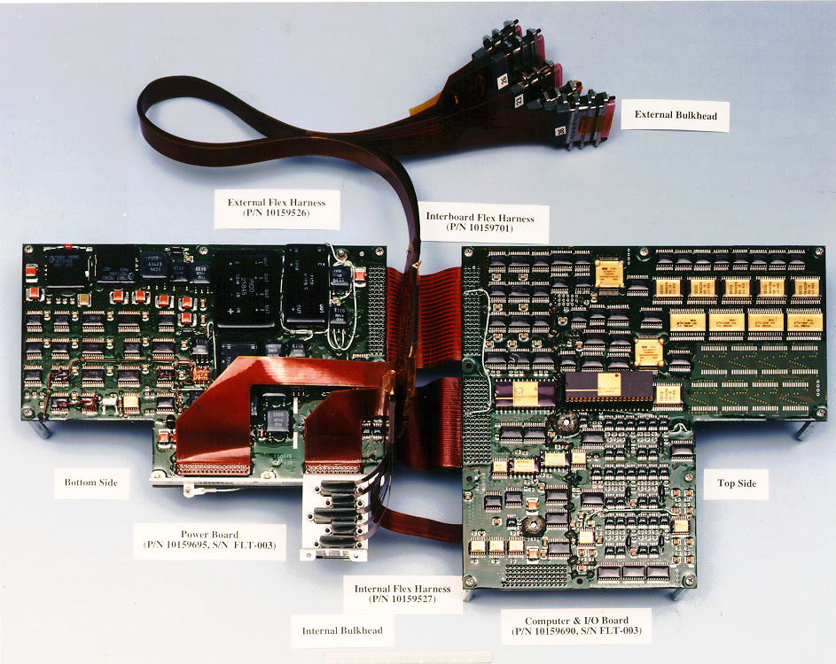
NASA Sojourner rover 8085 based computer
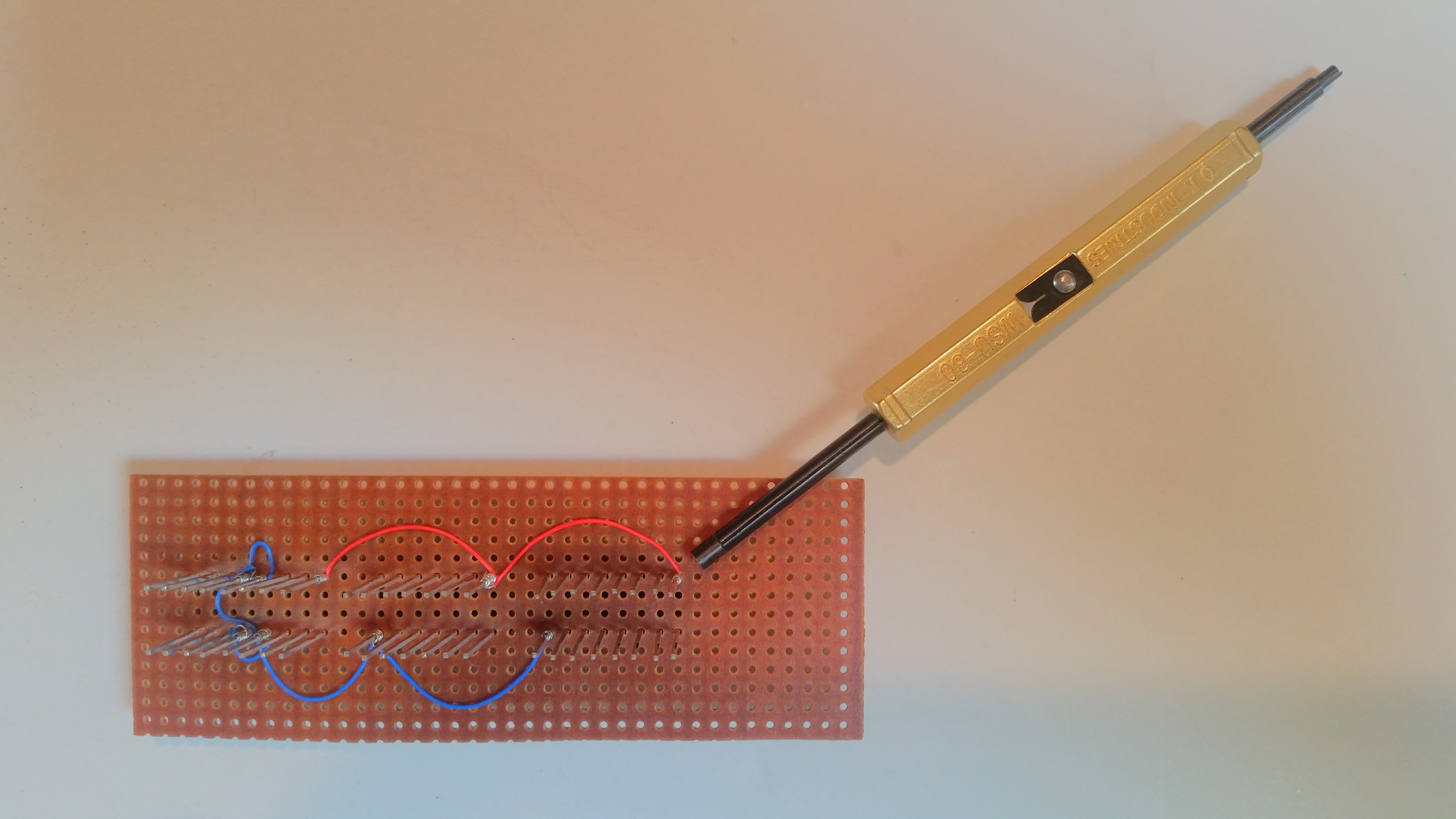
wirewrap breadboard with wirewrap tool
Electrical Engineering involves the application of electricity, electronics, and electromagnetism. Energy is available in various forms such as electrical, hydro, wind, and solar energy. An Electrical Engineer develops technologies to assist with the practical application of such energies. Electrical Engineers design components for electronic equipment, communications systems, power grids, batteries, motors, and more.
This page is intended to provide pointers to tools and software that can help with the engineering of electronic devices and electronic sensors. The software referenced here is all either free, inexpensive, or demo software so it can be tried without initially investing significant money. Where possible we've included a link to the site where you can get the latest version rather than a direct download of a possibly stale version.
Ohms law describes the motion of electrons through a circuit:
- V = I * R
where:
- V is the voltage between two points in the circuit
- I is the current flowing through that part of the circuit
- R is the resistance of that part of the circuit
The most fundamental electronic component is the resistor along with capacitors, inductors, and semiconductors including diodes and various types of transistors. While resistors resist the flow of any current, capacitors tend to resist the flow of constant current and inductors tend to resist the flow of variable current. Software tools that simulate the electronic circuitry you've created would allow you to test and debug the circuitry before building it. A common example of this type of application is SPICE (Simulation Program with Integrated Circuit Emphasis) which is an analog electronic circuit simulator.
The relationship of current and voltage with a capacitor in a circuit:
- I = C * deltaV / deltaT
where:
- I is the current flowing through that part of the circuit
- deltaV / deltaT is the change in voltage over the change in time
- C is the capacitance of that part of the circuit
The relationship of current and voltage with a inductor in a circuit:
- V = L * deltaI / deltaT
where:
- V is the voltage between two points in the circuit
- deltaI / deltaT is the change in current over the change in time
- L is the inductance of that part of the circuit

Electronic Component Symbols
| SPICE letter code | element | |
|---|---|---|
| B | FaAs field effect transistor - MESFET | semiconductor |
| C | capacitor | fundamental electronic component |
| D | diode | semiconductor |
| E | voltage controlled voltage source (VCVS) | |
| F | current controlled current source (CCCS) | |
| G | voltage controlled current source (VCCS) | |
| H | current controlled voltage source (CCVS) | |
| I | independent current source | power source |
| J | junction field effect transistor - JFET | semiconductor |
| K | coupled inductors | |
| L | inductor | fundamental electronic component |
| M | MOS field effect transistor - MOSFET | semiconductor |
| Q | bipolar junction transistor - BJT | semiconductor |
| R | resistor | fundamental electronic component |
| V | independent voltage source | power source |
| X | sub circuit |
Beyond fundamental analog electronic components there are electronic sensors (which often behave like a resistor or transistor), electro-mechanical devices that move mechanical things (solenoids and motors behave like inductors), and digital electronics (used to interface with or build digital computer processors and memory). Fundamental digital electronic components are the and-gate, or-gate, exclusive-or-gate, and not-gate.
Connecting these electronic components in a useful configuration produces an electronic circuit. Some common circuits include amplifiers used to increase weak sensor signals, H-bridges used to control current to motors, and analog to digital converters (ADCs) used to convert analog sensor signals to digital signals used by digital electronics and computers. These electronic circuits can be combined in ICs (integrated circuits) or on circuit boards. While it's unlikely that you'll be designing and manufacturing your own IC, once you have your electronic circuit designed you might want to build your own circuit board. Other helpful tools include applications that allow you to layout the placement of components on a circuit board and figure out how to route connections. If you design your own circuit board, you can fabricate it yourself or companies will fabricate a circuit board for you from your design.
When assembling circuits whether on solderless breadboard, or wirewrap breadboard, or soldering to printed circuit boards, you will need to know how to tell the characteristics of electronic components. For example, not all resistors have the same resistance. Most components have a code on them indicating what characteristics they have. In the case of resistors, they have a color code consisting of 3 or 4 colored stripes. The first two stripes indicate the first two significant figures of the resistance. The third stripe is the decimal multiplier. The value is given in ohms. If the fourth stripe exists, it indicates the tolerance. For example, a resistor with colored bands of brown, black, and red has the resistance of 1 0 * 10^2 or 1000 ohms, and a resistor with colored bands of red, red, and black has the resistance of 2 2 * 10^1 or 220 ohms.
| color | significant figure | decimal multiplier | tolerance % |
|---|---|---|---|
| black | 0 | 10^0 = 1 | 20 |
| brown | 1 | 10^1 = 10 | 1 |
| red | 2 | 10^2 = 100 | 2 |
| orange | 3 | 10^3 = 1000 | 3 |
| yellow | 4 | 10^4 | 4 |
| green | 5 | 10^5 | 5 |
| blue | 6 | 10^6 | 6 |
| violet | 7 | 10^7 | 7 |
| gray | 8 | 10^8 | 8 |
| white | 9 | 10^9 | 9 |
| gold | 10^-1 = 0.1 | 5 | |
| silver | 10^-2 = 0.01 | 10 | |
| no color | 20 |
In the case of capacitors, some will have their capacitance value written on them. However, ceramic disk capacitors have a three digit code. The first two digits indicate the first two significant figures of the capacitance. The third digit is the decimal multiplier. The value is given in picoFarads.
Some retailers for electronics and other parts are:
