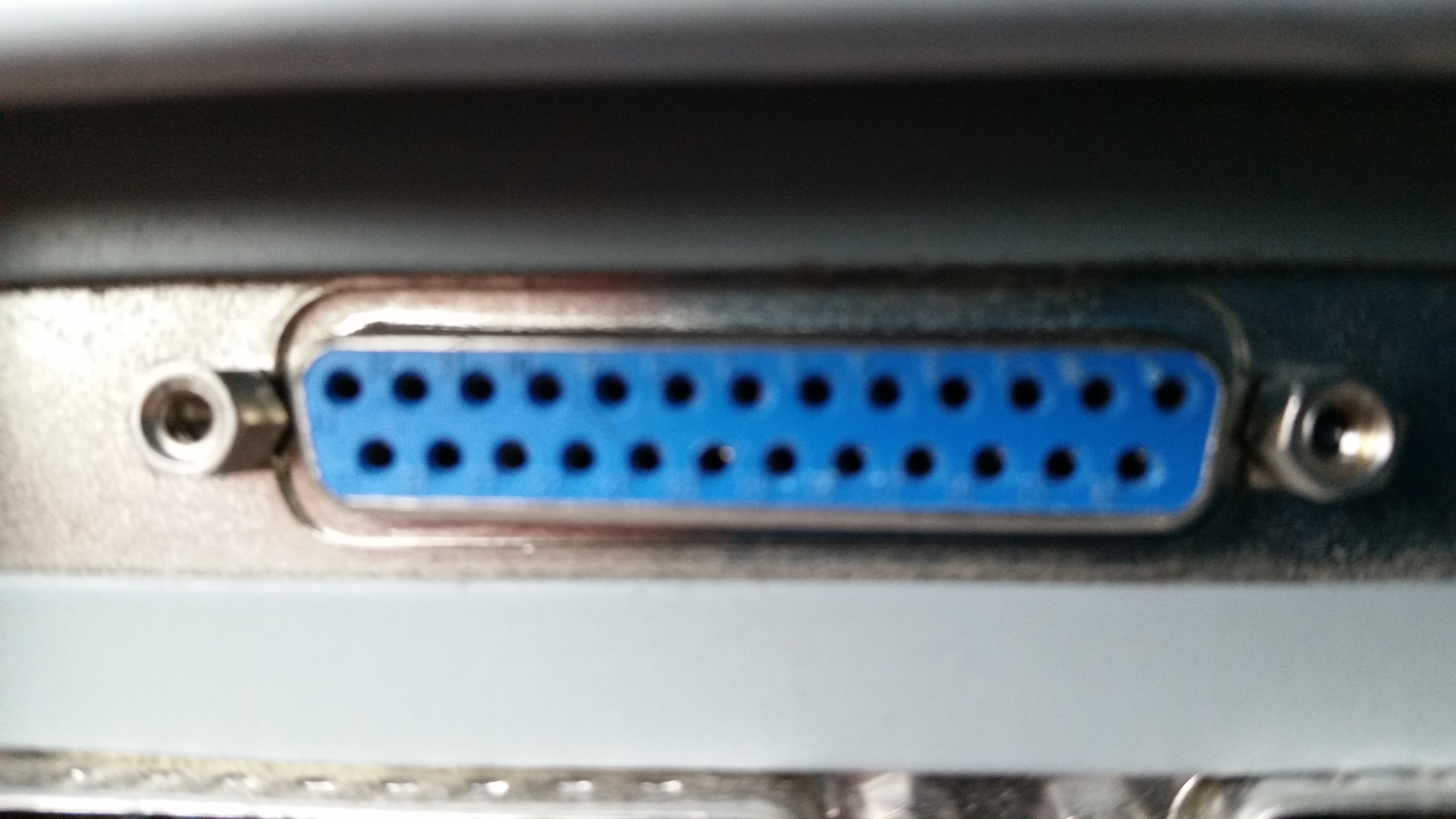
a 25 pin parallel printer port built into an older personal computer
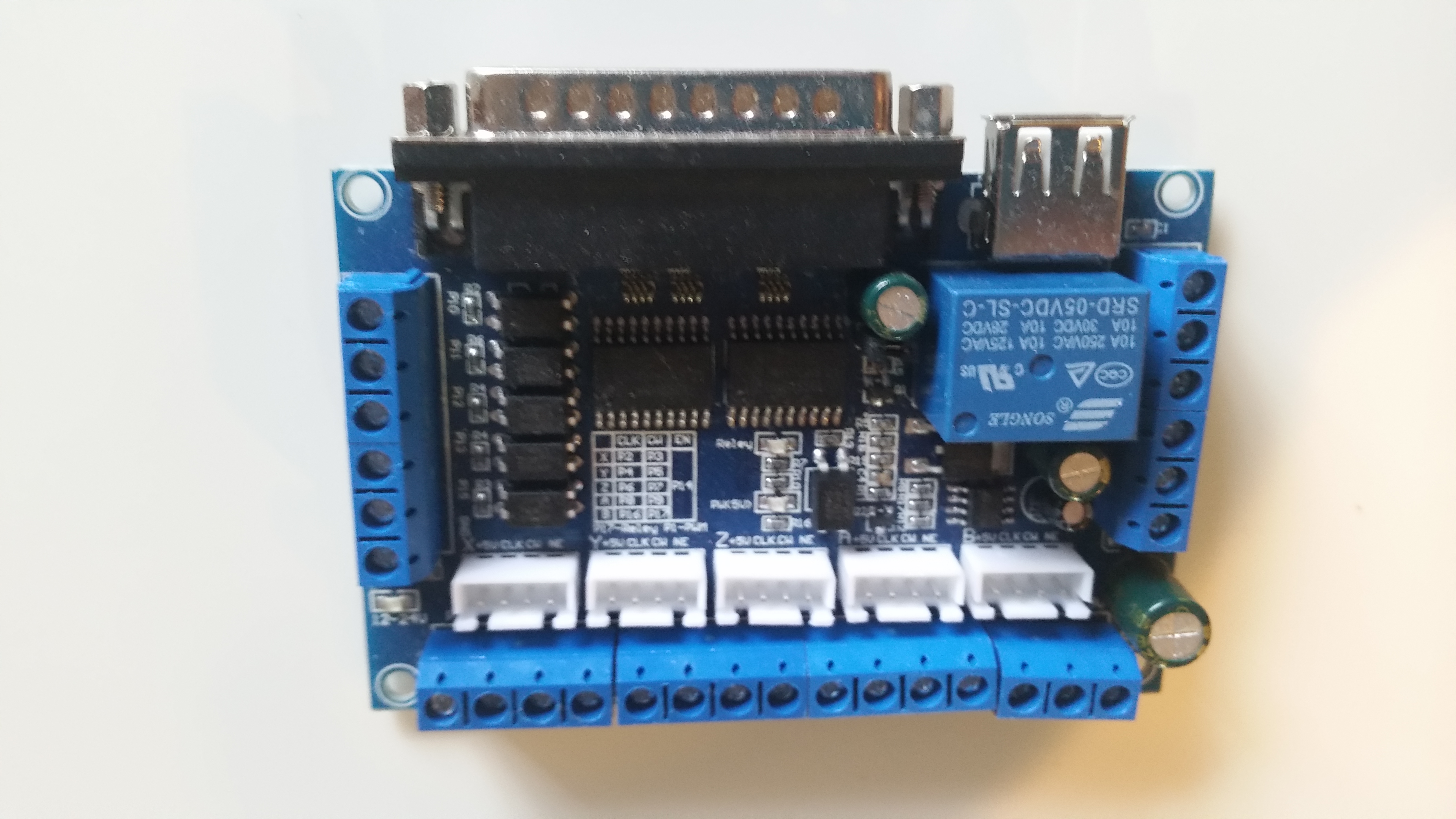
a Mach3 CNC controller designed to be used with a 25 pin parallel printer port built into an older personal computer
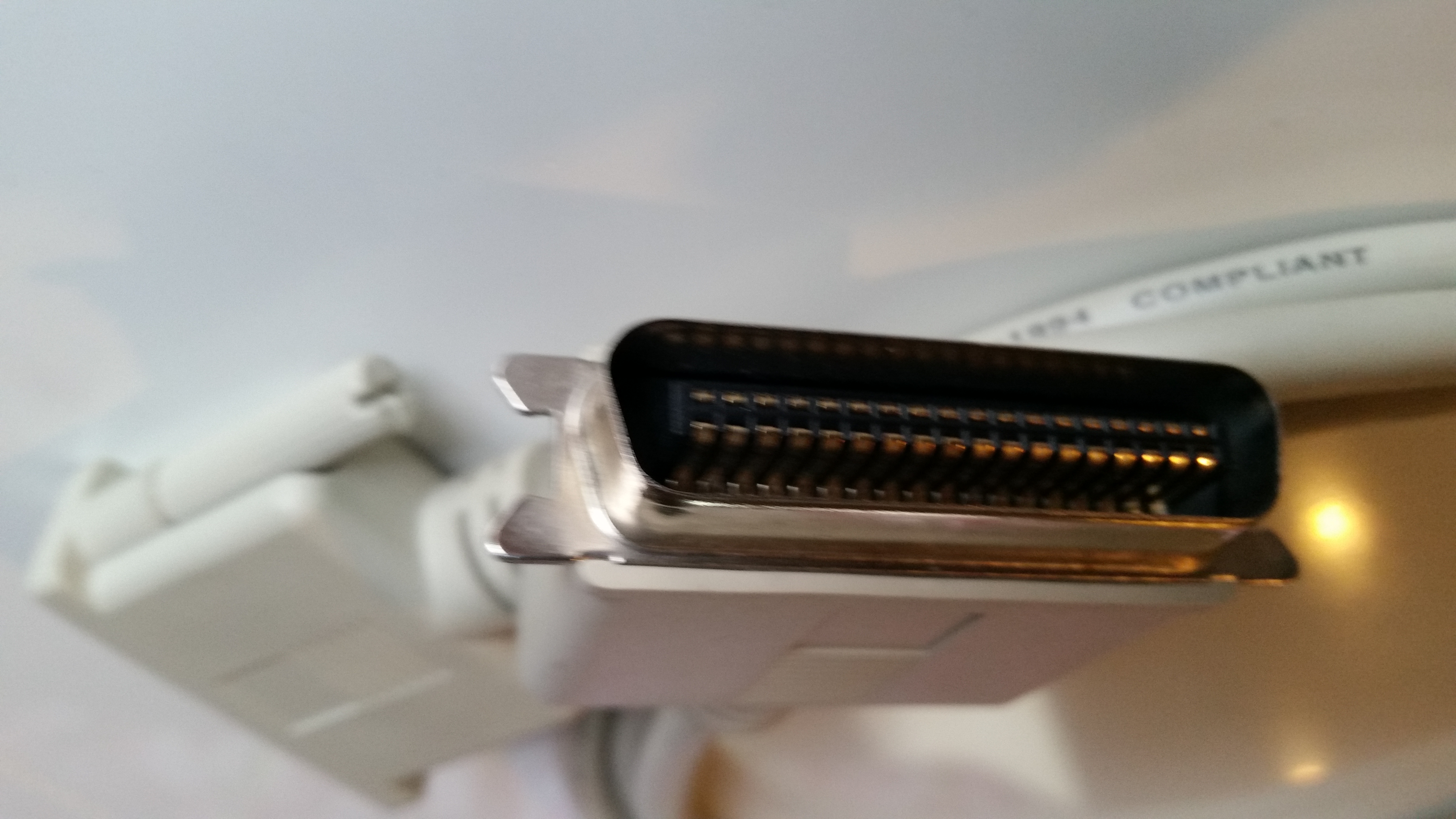
a 36 pin Centronics port
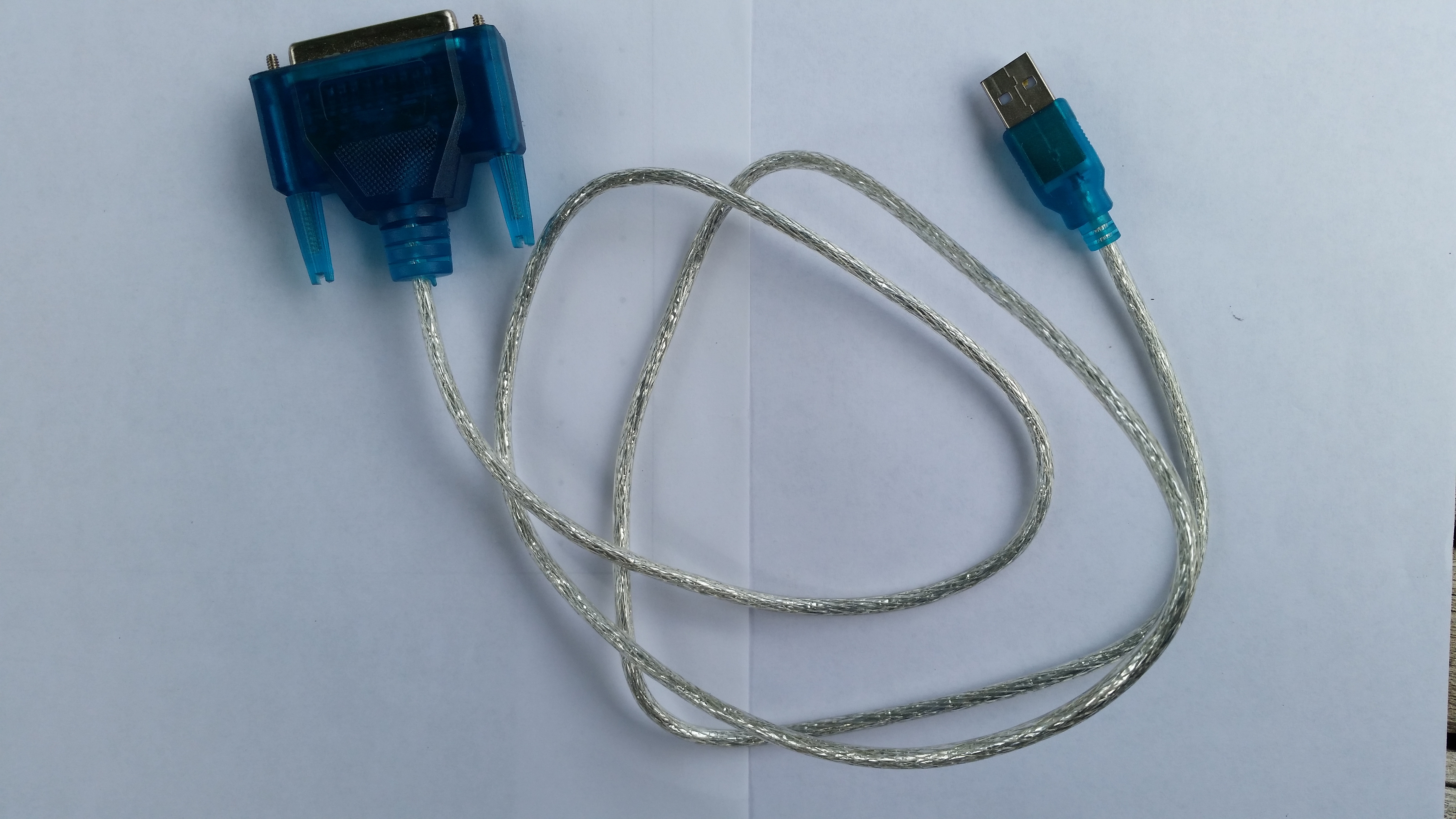
a USB to Parallel port cable for modern personal computers with USB support but no parallel printer ports
with an older PC, through a parallel port (also known as a Centronics port or IEEE-1284 port)
or with a newer PC, through a USB port using a USB to parallel port cable
If you want to build your own control system, you can review some options at Control Systems. The option described here, to build your own controller device, is that you could leverage a PC and a parallel printer port or a USB parallel printer adapter. For that option, first lets cover some background on the approach, and then the steps to take to build this controller.
Early dot matrix printers had a print head consisting of a row of seven to nine metal pins connected to solenoids. When power was applied to the solenoids, the pin was pulled forward to strike the paper and leave a dot. The parallel port was designed to make it simple to set or clear these pins. However, instead of a printer head, a parallel port could control any number of other items like turning on an electric motor for a wheel on a robot or switching on or off a control valve for a thruster on a spacecraft.
A MACH3 CNC system is an example of a parallel printer port being used to control a CNC machine from a personal computer.
With an older personal computer with a parallel port built in,
using DOS or Windows, you can copy files to pseudo files with the name PRN, LPT1, LPT2, or LPT3
by doing:
copy {filename} PRN
This is a simplistic way to send a file byte by byte to the parallel port
changing the state of the parallel port pins.
More interesting would be to do this programmatically by opening the PRN or LPT# pseudo file,
and writing bytes to the pseudo file as needed to change the start of the parallel port pins.
With this configuration you should be able to run commands like:
copy {filename} LPT1
... to send files to a printer like an older EPSON FX Series dot matrix printer.
However, if you want to use the parallel ports data bits to control items like an LED light or an electric motor,
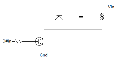
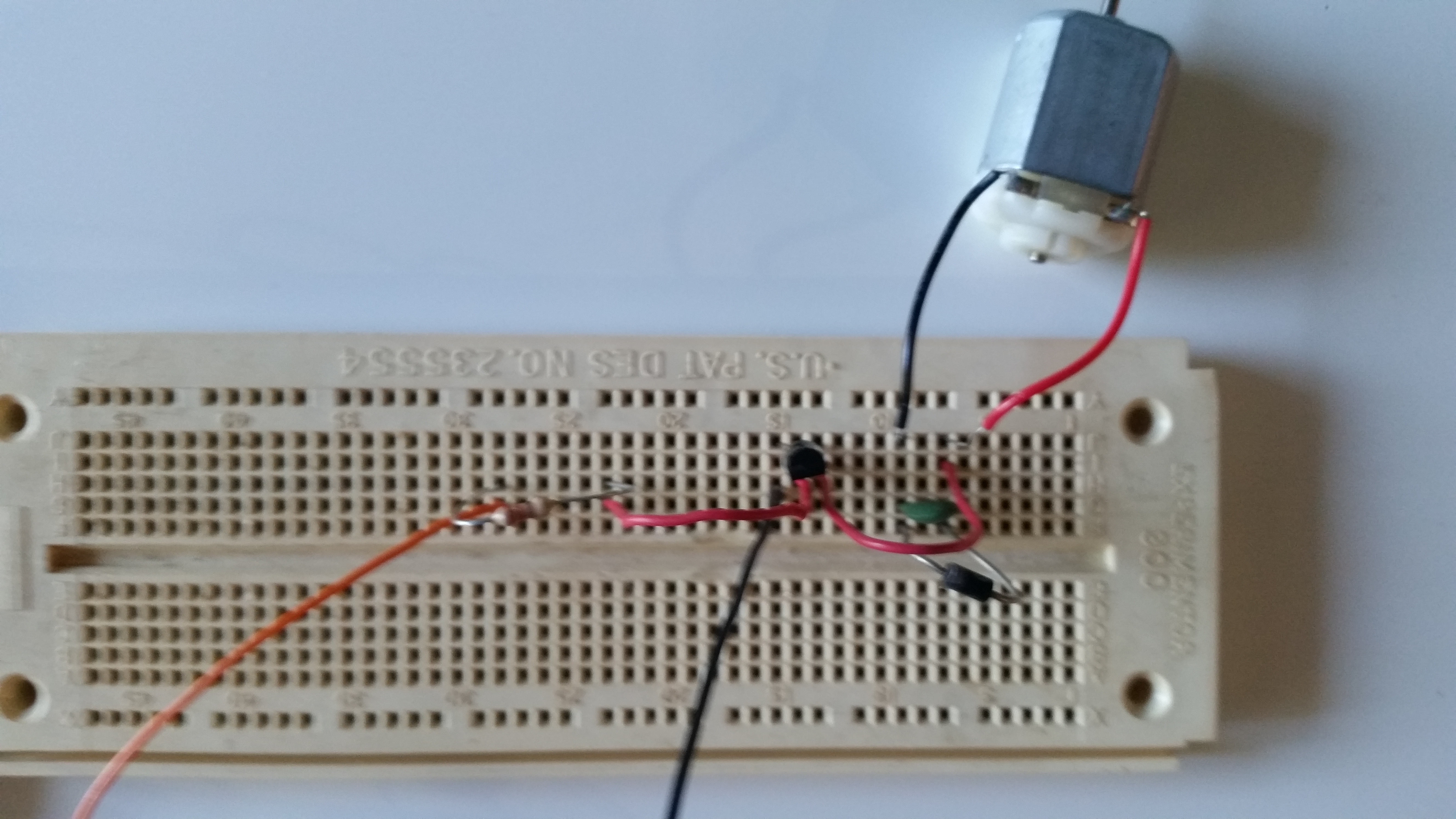
depending on your parallel port, you will probably need electronics that respond like an older printer.
Otherwise you'll only be able to send one byte,
which will cause the computer to think that the printer is busy and it won't send any more bytes of data.
The parallel or centronics port handshake uses the following pattern.
First, data is presented on the parallel port pins 2 to 9 representing data bits 0 through 7. The computer then lowers the Strobe line (pin 1), waits a minimum of 1 μS, and then raises the Strobe line. The data bits would normally be read by the printer on the rising edge of the Strobe line. The printer electronics would indicate that it is busy processing the data by raising the Busy line (pin 11). The computer then checks to see if the printer electronics are indicating it is busy, and waits for the Busy line to go low. Once the printer has accepted data, it will acknowledge receiving the data by a low pulse, about 5 μS, on the Ack line (pin 10). Quite often the computer will ignore the Ack line to save time, but it won't ignore the Busy line.
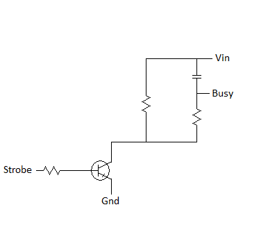
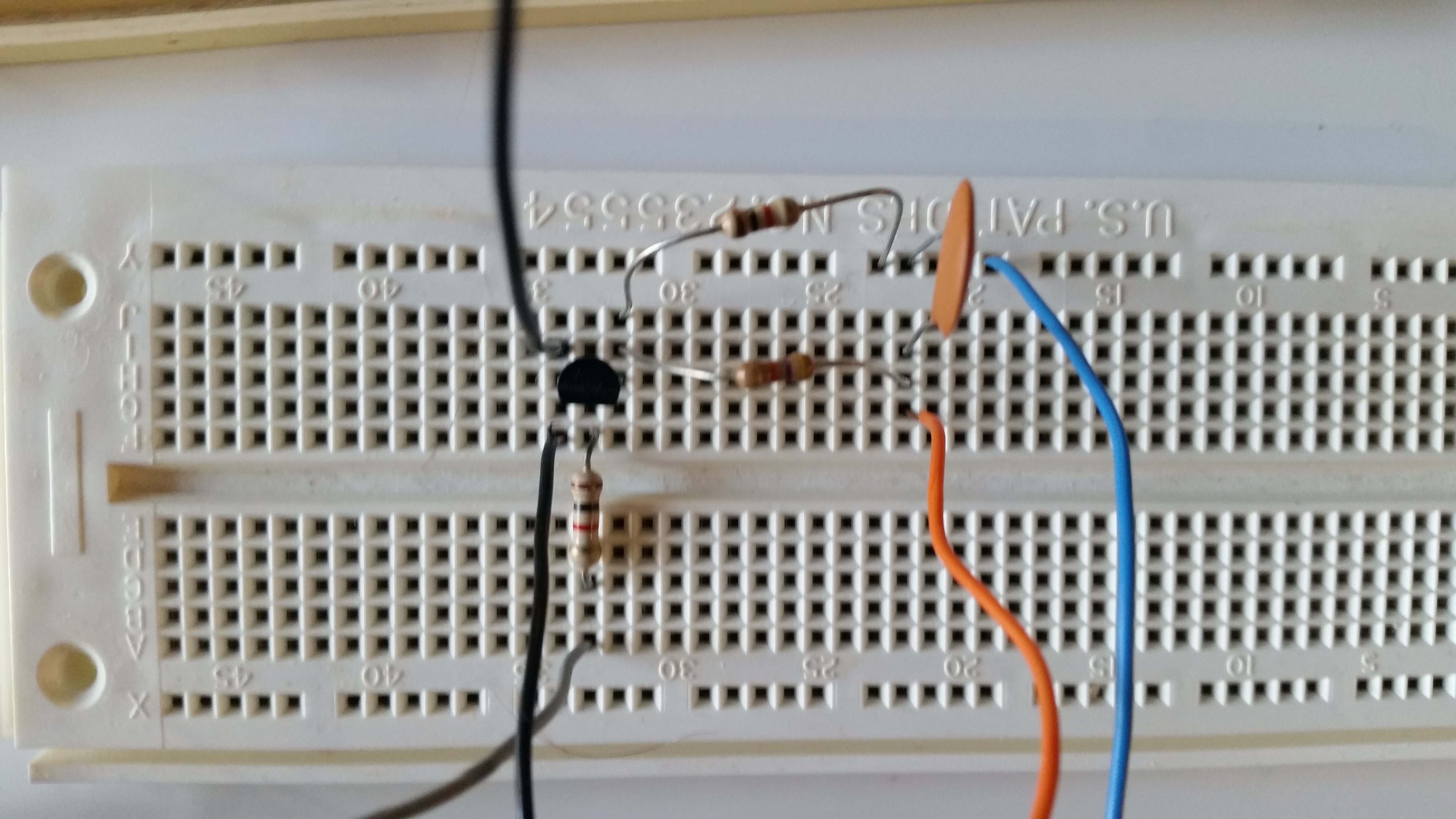
Thus, depending on the parallel port hardware or cable you have, any electronics you wire up may need to respond as printer electronics would. Your electronics might not need to do anything. They might need to keep the Busy line (pin 11) low so the computer sees that it can keep sending data. Alternately they might need to raise the Busy line and then lower it to indicate the data has been accepted. In rare cases your electronics might need to both raise and lower the Busy line and also lower and raise the Ack line (pin 10). Other parallel port input pins like the Paper-Out line (pin 12), Select line (pin 13), and Error line (pin 15) should be kept low.
| Pin (DB25) | Pin (36 pin) | Signal Name | Direction |
|---|---|---|---|
| 1 | 1 | Strobe | Out Control |
| 2 | 2 | D0 | Out Data |
| 3 | 3 | D1 | Out Data |
| 4 | 4 | D2 | Out Data |
| 5 | 5 | D3 | Out Data |
| 6 | 6 | D4 | Out Data |
| 7 | 7 | D5 | Out Data |
| 8 | 8 | D6 | Out Data |
| 9 | 9 | D7 | Out Data |
| 10 | 10 | Ack | In Status |
| 11 | 11 | Busy | In Status |
| 12 | 12 | Paper-Out | In Status |
| 13 | 13 | Select | In Status |
| 14 | 14 | Linefeed | Out Control |
| 15 | 32 | Error | In Status |
| 16 | 31 | Reset | Out Control |
| 17 | 36 | Select-Printer | Out Control |
| 18-25 | 16,17,19-30,33 | Ground | Gnd |
