How to Use Simple CB App - A Simple printed Circuit Board auto router
To use Simple CB, start by downloading the Windows app to your Windows computer.
Download Simple CB (SimpCB.msi)  for 32-bit Windows (works on 64-bit Windows)
Simple CB
In early electronics, hobbyists and students used nails in wooden breadboards (used to slice bread on) to anchor electronic components and connected the components with wires and solder to form circuits.
Today when assembling circuits, hobbyists and students can use solderless breadboards, wirewrap perfboards, or printed circuit boards (aka PCB).
For solderless breadboards or wirewrap perfboards, insulated wires from one connection to another can cross other insulated wires without any significant problems to the circuit.
However, while good for short term prototypes, these boards aren't very durable.
For printed circuit boards, wires are replaced by printed copper traces.
The printed traces can not cross, unless they run on a different layer of the board.
Most printed circuit boards have two layers, on the top and bottom surface of the board, which allows traces to cross one other trace at any point.
In order to etch a printed circuit board it is necessary to route the traces so they don't cross except if they are on different layers.
Simple CB (Simple printed Circuit Board) is a circuit board auto router that might be helpful to the hobbyist or student who wishes to design and etch their own electronic printed circuit boards (PCB).
A printed circuit can replace all hand wired circuitry with copper traces etched on a board.
Simple CB only allows a resolution of 0.05 inch between traces, but defaults to 0.1 inch between traces, which should allow the use of most discrete components and DIP and SIP chips.
Also, a resolution of 0.05 inch is about the finest resolution that can be successfully etched by hand and 0.1 inch is about the resolution that can be etched easily.
The current implementation allows you to control the size of the circuit board, up to 12.8" x 4.0" with 0.1 inch resolution or 6.4" x 4.0" with 0.05 inch resolution.
This is large enough to support
PC/104
and
PCI-104
form factor boards, which are roughly 3.6 x 3.8 inches, and fit well in 10 x 10 cm CubeSats.
The current implementation also expects the board to be a double sided circuit board.
Simple CB is a 32-bit Windows applications that can run on 32-bit or 64-bit Windows.
It is not digitally signed so you will get a warning when you install it that the author is unknown.
If you get a dialog inidicating 'Windows protected your PC', select 'More info', and then 'Run anyway'.
Updates happen a few times a year so if something isn't working, make sure you have the latest version installed.
Also, if you identify any problems please report them to the teraKUHN project.
Walk Through of using Simple CB:
Simple CB Menu Commands Reference
Writing the PaRTs file or the LAYout file
Simple CB uses two files to describe the circuit board that you want to route.
For the first file, you can use either a *.prt or *.lay file to describe the components on the circuit board.
The *.prt and *.lay file each contain a list of components, one per line.
The *.prt file is described with the following syntax:
- C[name] [width]
- S[name] [pins]
- D[name] [pins] [width]
- Z[name] [pins] [width]
- E[name] [hor-pos] [ver-pos] [pins] [width] [direction]
The *.lay file additionally describes the layout of all of the components on the circuit board.
The *.lay file is described with the following syntax:
- C[name] [hor-pos] [ver-pos] [width] [direction]
- S[name] [hor-pos] [ver-pos] [pins] [direction]
- D[name] [hor-pos] [ver-pos] [pins] [width] [direction]
- Z[name] [hor-pos] [ver-pos] [pins] [width] [direction]
- E[name] [hor-pos] [ver-pos] [pins] [width] [direction]
- P[name] [hor-pos] [ver-pos] [surface]
- R[name] [hor-pos] [ver-pos] [surface]
where all fields in [] are required and have the following meaning:
C indicates a 2 lead discrete Component (resistor, capacitor, etc.)
S indicates a Single Inline Package (SIP) component
D indicates a Dual Inline Package (DIP) component
Z indicates a Zigzag Inline Package (ZIP) component (supported in version 1.6 and later)
E indicates an Edge connector
P indicates a contact Pad (used to form unique components)
R indicates a Reserved location (used to help the router)
[name] is a unique identifier representing the component composed of letters, digits, and underscores starting with a letter or underscore
[hor-pos] indicates the horizontal position in 0.1" units
[ver-pos] indicates the vertical position in 0.1" units
[pins] is the number of connections the component has
[width] is the width between the 2 contacts or rows of contacts in a discrete Component or DIP or ZIP
[direction] orientation of component which can be Up, Down, Left, or Right
[surface] is the surface of the circuit board which can be Top, or Bottom
When using the Generate Layout (previously Full Layout) command rather than the Layout command, the hor-pos, ver-pos, and direction values for C, S, D, and Z component types are ignored and generated by Simple CB dynamically.
There must still be a value for these fields in the *.lay file, but since they are ignored they can be set to zero.
As an alternative, you can create a Parts file with a *.prt file extension (instead of *.lay extension).
As of version 1.6 of Simple CB, *.prt files do not need nor allow hor-pos and ver-pos and direction values for C, D, and Z component types.
However, you must use Generate Layout (previously Full Layout) with a *.prt file and can not use the Specified Layout command as there is no specified layout in the parts file.
Also, to use Generate Layout, you must have written a ROUter file since generating a layout requires knowledge of how components will be connected.
In addition to directly editing the *.lay file, components can be placed on the board by double clicking the left mouse button on an unoccupied cell at the location where the new component is to be placed.
This will bring up a dialog that the remaining information about the component needs to be entered in.
Once this information is provided, Simple CB will then update the *.lay file and the board window with the new component.
Writing the Route file
Simple CB uses two text files to describe the circuit board that you want to route.
For the second file, you use the *.rou file to contain the net list which describes how the components are to be connected.
The *.rou file contains lines indicating each component pin designation in a node followed by a line with N and optionally the name of the electrical node.
Each additional electrical node is automatically started after the previous is ended.
The last line of the file should contain an N.
Describe each node with the following syntax:
- [component-type][name] [contact]
- [component-type][name] [contact]
- ...
- N
where all fields in [] are required and have the following meaning:
[component-type] is one of C, S, D, Z, E, P, or R where:
C indicates a 2 lead discrete Component (resistor, capacitor, etc.)
S indicates a Single Inline Package (SIP) component
D indicates a Dual Inline Package (DIP) component
Z indicates a Zigzag Inline Package (ZIP) component (supported in version 1.6 and later)
E indicates an Edge connector
P indicates a contact Pad (used to form unique components)
R indicates a Reserved location (used to help the router)
[name] is a unique identifier representing the component composed of letters, digits, and underscores starting with a letter or underscore
[contact] the specific pin or contact number of the component
In addition to directly editing the *.rou file, component pin designations can be added to the end of the *.rou file by double clicking the left mouse button on an occupied cell.
However, you must first run one of the Layout commands to create a clean circuit board with your components on it.
Then when a component pin is double clicked the designation for it will be added to the end of the *.rou file.
It is still necessary to directly edit the *.rou file to indicate the nodes and may be necessary to directly edit it to place the designation in the correct node.
Layout of the Components
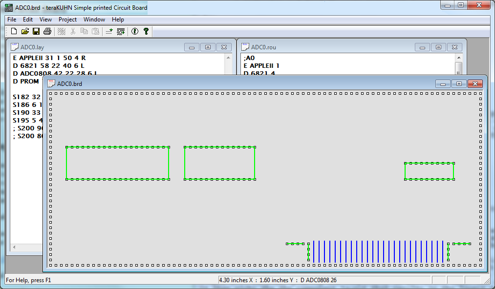
Component layout in Simple CB
Simple CB uses two text files to describe the circuit board that you want to route.
The first file, the *.prt or *.lay file, describes the parts list and optionally the layout of the components on the circuit board.
The other file, the *.rou file, contains the net list which describes how the components are to be connected.
To route a circuit board you normally start by running one of the Layout commands to create a clean circuit board with your components on it.
However, if you want Simple CB to figure out where to place components on the board, use the Generate Layout (previously Full Layout) command instead of the Layout command.
The *.lay file still needs to have component placement information in it, but it will be ignored for simple Components, SIPs, DIPs, and ZIPs.
Simple CB will consider placing the components in different locations and analize the density of traces that would result.
It then picks the the component layout that results in the lowest trace density.
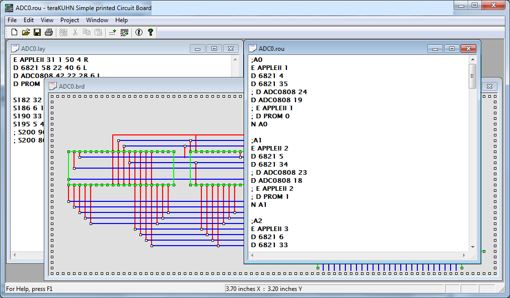
Auto Routing the Circuit Board
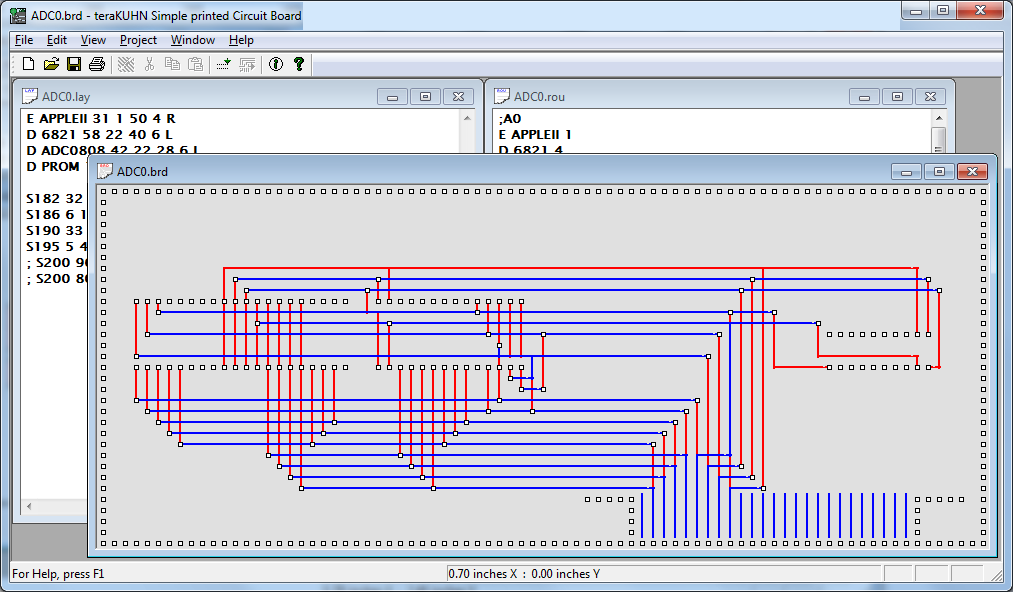
Circuit routing in Simple CB
Simple CB uses two text files to describe the circuit board that you want to route.
The first file, the *.prt or *.lay file, describes the parts list and optionally the layout of the components on the circuit board.
The other file, the *.rou file, contains the net list which describes how the components are to be connected.
Two commands are used to route the circuit board, the Layout command and the Router command.
To route a circuit board you start by running the Layout command to create a clean circuit board with your components on it.
The next step, to actually route the circuit board, is to run the Router command with the results from the just run Layout command.
An hour glass will then appear, and as the router completes nodes it will update the board windows.
When the auto router completes, the regular cursor will return and if any nodes failed to route, a log file will be displayed that lists the nodes that failed.
Manual Routing the Circuit Board
Simple CB is primarily an auto router and thus doesn't directly allow manual routing.
However, you can use sequences of reserved cells to manually control a trace.
To do this you need to create the reserved cells in the *.lay file, and you need to specify the reserved cells in the appropriate node in the *.rou file.
The auto router will then include these cells in the trace for the node they are specified in.
This will cause the auto router to follow these reserved cells and thus you can manually control the trace.
In addition to directly editing the *.lay file and the *.rou file, sequences of reserved cells can be added to both files simultaneously by clicking down the left mouse button where a sequence is to start and letting up on the left mouse button where the sequence is to end.
Note that either the X coordinate or the Y coordinate of the two points needs to stay constant.
Simple CB will then update the *.lay file and the board window with the new reserved cells.
The designation of the reserved cells will be added to the end of the *.rou file.
It is still necessary to directly edit the *.rou file to place the designations in the correct node.
Generating Output from the Circuit Board
Once you have a routed circuit board (*.brd file) you can view it in Simple CB.
You can also print the circuit board on any printer from Simple CB.
To create your own circuit board, you should purchase a basic kit designed to supply the hobbyist or student with all materials necessary to construct a printed circuit board.
The printed circuit replaces all hand wired circuitry with copper lines drawn on a board.
Draw these lines using a resist ink pen on a copper board.
To obtain copper lines, the board is immersed in an etching solution which dissolves all the copper not coated with the resist ink.
When the resist ink dissolves, the printed circuit board remains.
There are various methods to transfer the routed circuit to the copper board before etching.
One way is to impress the circuit onto the board is by placing a piece of carbon paper face down between a print out of the routed circuit and the copper board, and then trace the circuit with a ball-point pen.
Check the diagram to be sure all lines have been drawn.
Then trace over the lines on your copper board, making a heavy dot where the holes are to be drilled.
The ink will dry in a minute.
Now retrace the lines with the resist ink pen to insure complete coverage.
Allow time to dry.
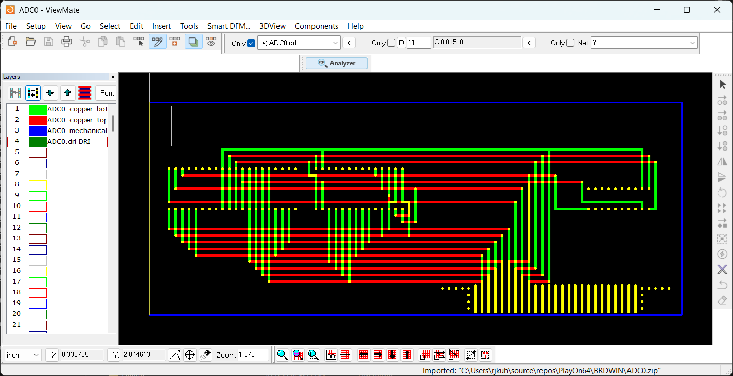
ViewMate screenshot of Simple CB RS-274X export
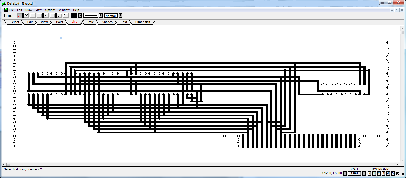
Screenshot of Simple CB dxf export
Simple CB also includes a number of export options to generate different file formats used by other systems.
These currently include RS-274X CNC/Gerber files, legacy RS-274D CNC/Gerber files, and dxf CAD file.
Once you have a routed circuit board, you can export the board file to a set of Gerber files (*.gbr *.drl) or legacy (*.gtl *.gbl *.cnc) which are used by many prototype board etchers.
The Gerber file format is the de facto standard used by printed circuit board (PCB) industry software to describe PCBs.
Extended Gerber or RS-274X and legacy Standard Gerber or RS-274-D are specific variants of the G-Code or RS-274 file format which is often used for numerical control (NC) of automated machine tools.
Most PCB manufacturers will accept Extended Gerber or RS-274X files.
Gerber files can contain all the data required to print all the layers of a printed circuit board.
For a double sided printed circuit board, you need two files, top and bottom, for each thing being printed on the board.
Things that might be printed include the copper circuit trace, solder mask, solder paste, and silkscreen.
At a minimum you need the top and bottom copper circuit traces, which is what Simple CB provides.
Finally, a drill file will also be required to drill holes for connecting the top layers to the bottom layers and mounting components.
Link to Gerber file format which is used by most PCB manufacturers
Link to alternate Gerber file format
Here are the typical Gerber file extensions and their meanings.
- NC Drill (*.drl, *.cnc, or *.ncd)
- Top Copper Layer (*copper_top.gbr or *.gtl)
- Bottom Copper Layer (*copper_bottom.gbr or *.gbl)
- Top Solder Mask (*mask_top.gbr or *.gts)
- Bottom Solder Mask (*mask_bottom.gbr or *.gbs)
- Top Overlay/Silkscreen (*silkscreen_top.gbr or *.gto)
- Bottom Overlay/Silkscreen (*silkscreen_bottom.gbr or *.gbo)
- There are other layer types, but these are the most common.
For prototypes you would typically only need the Drill, Top, and Bottom layer files and these are what Simple CB generates and exports.
To verify that the Gerber files exported are valid, you can download the free
PentaLogix ViewMate
gerber viewer and open the gerber files to view them.
Alternately you can use the
Ucamco web page
gerber viewer.
Commands
File menu commands
The File menu offers the following commands:
| New |
Creates a new document. |
| Open |
Opens an existing document. |
| Close |
Closes an opened document. |
| Save |
Saves an opened document using the same file name. |
| Save As |
Saves an opened document to a specified file name. |
| Export as CNC/Gerber |
Exports a routed circuit board as Gerber files. |
| Export as DXF |
Exports a routed circuit board as a dxf CAD file. |
| Print |
Prints a document. |
| Print Preview |
Displays the document on the screen as it would appear printed. |
| Print Setup |
Selects a printer and printer connection. |
| Exit |
Exits Simple CB. |
Edit menu commands
The Edit menu offers the following commands:
| Undo |
Reverse previous editing operation. |
| Cut |
Deletes data from the document and moves it to the clipboard. |
| Copy |
Copies data from the document to the clipboard. |
| Paste |
Pastes data from the clipboard into the document. |
| Delete |
Deletes data from the document. |
| Find |
Searches for characters or words in a document. |
| Replace |
Replaces characters or words in a documents. |
| Repeat |
Repeat the last search or replace. |
| Parts/Layout File |
Open and bring to the forground either the Parts or Layout file. |
| Route File |
Open and bring to the forground the Route file. |
View menu commands
The View menu offers the following commands:
| Toolbar |
Shows or hides the toolbar. |
| Status Bar |
Shows or hides the status bar. |
| Zoom Out |
Decrease magnification in the active circuit board view. |
| Zoom In |
Increase magnification in the active circuit board view. |
| Overlay |
Overlay top and bottom surface in the active circuit board view. |
Project menu commands
The Project menu offers the following commands:
| Options |
Set Circuit Board Options. |
| Use Specified Layout |
Layout Circuit Board based on component locations specified in Layout file. |
| Generate Layout (previously Full Layout) |
Layout Circuit Board based only on list of components. |
| Router |
Route Circuit Board. |
Window menu commands
The Window menu offers the following commands, which enable you to arrange multiple views of multiple documents in the application window:
| New Window |
Creates a new window that views the same document. |
| Cascade |
Arranges windows in an overlapped fashion. |
| Tile Horizontal |
Arranges windows horizontally in non-overlapped tiles. |
| Tile Vertical |
Arranges windows vertically in non-overlapped tiles. |
| Arrange Icons |
Arranges icons of closed windows. |
| Window 1, 2, ... |
Goes to specified window. |
Help menu commands
The Help menu offers the following commands, which provide you assistance with this application:
| Online Help |
Offers you a link where you can get help. |
| About |
Displays the version number of this application. |
Disclaimer, Comments on Shareware, and Copyright
Simple CB is distributed 'as is', so the user bears all responsibility for testing that the functionality is acceptable.
Use Simple CB at your own risk.
If this software has undesired effects, your sole recourse is to discontinue use of it.
That said, we hope you enjoy using this software and are able to get some practical work accomplished with it.
Feel free to write to us if you have questions, suggestions, feeback, or bug reports regarding it.
Contact us at the teraKUHN project.
Simple CB is a shareware program.
Please help more people learn about it by pointing friends, classmates, and co-workers at the download location for them to try it.
Please do not redistribute it on your own.
If you use Simple CB on a regular basis, you are required to register it.
With a registration you will receive an email notification when the next version of the software is available.
To register through PayPal send $5.50 US to teraKUHN@yahoo.com with the program name 'Simple CB' in the note to seller.
Alternatively send a check for $5.00 US payable to R. J. Kuhn and a note with your email address and the program name 'Simple CB' to:
R. J. Kuhn
5412 158th Pl NE
Redmond, WA 98052
Software Copyright (C) 1993 - 2000, 2022 - 2025 R. J. Kuhn - All Rights Reserved
Text Copyright (C) 2019 - 2026 R. J. Kuhn.
Please note that you are not allowed to reproduce or rehost this page without written permission.