How to Build an Arduino Based Controller Systems
If you want to build your own control system, you can review some options at
Control Systems.
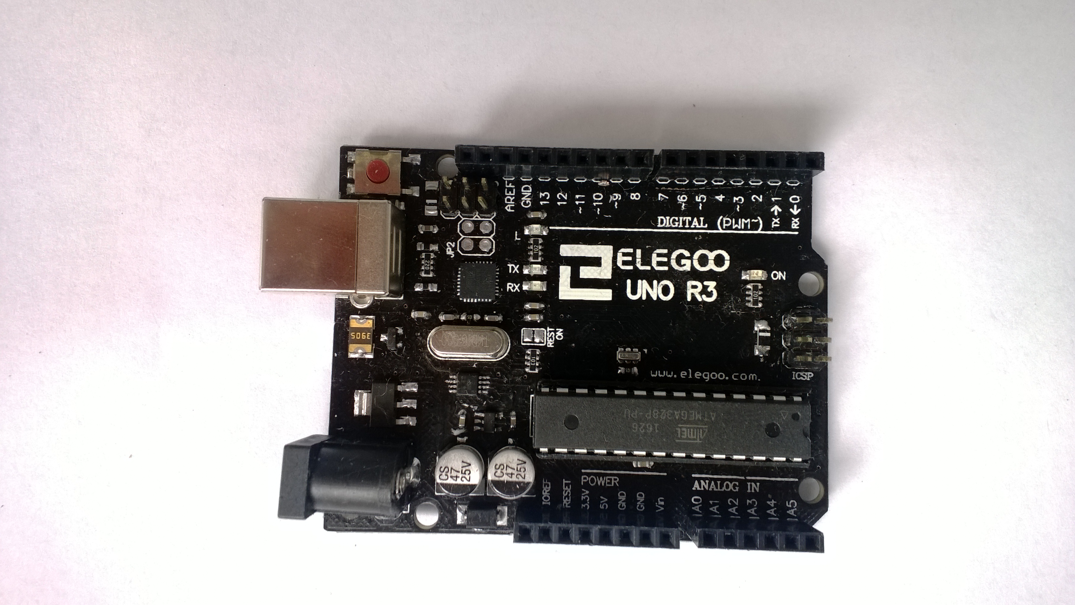
The option described here, to build your own controller device, is that you could leverage an Arduino device.
For that option, first lets cover some background on the approach, and then the steps to take to build this controller.
Unlike smartphones or PCs, Arduino boards (and other prototype development boards) have digital output options built into them.
Typically the large number of digital output options makes it easier for them to control a variety of external actuators.
If you want to use data ports to control items like an LED light or an electric motor,
you won't need additional electronics for any handshake.
However, you shouldn't wire up a digital output directly to a motor since a motor will probably draw more current than the digital output is rated for.
That said, these built in digital output options aren't always mapped to I/O addresses or memory addresses the same in every board or even chip.
For example, the table below shows the I/O addresses for the AVR ATmega328 (typically used in the Arduino Uno board) and the radiation tolerant AVR ATmegaS128.
Because of these differences in digital I/O locations, programmers are encouraged to use macros, functions, or procedures in the high level programming languages that will map I/O operations to the appropriate address for the chip being used.
Arduino / AVR port pins
| ATmega328 IO Address |
ATmega328 Memory Address |
ATmega128 IO Address |
ATmega128 Memory Address |
Signal Name |
Direction |
| 0x05 |
0x25 |
0x18 |
0x38 |
PORTB0 |
Out Data |
| 0x05 |
0x25 |
0x18 |
0x38 |
PORTB1 |
Out Data |
| 0x05 |
0x25 |
0x18 |
0x38 |
PORTB2 |
Out Data |
| 0x05 |
0x25 |
0x18 |
0x38 |
PORTB3 |
Out Data |
| 0x05 |
0x25 |
0x18 |
0x38 |
PORTB4 |
Out Data |
| 0x05 |
0x25 |
0x18 |
0x38 |
PORTB5 |
Out Data |
| 0x05 |
0x25 |
0x18 |
0x38 |
PORTB6/XTAL1/TOSC1 |
Out Data |
| 0x05 |
0x25 |
0x18 |
0x38 |
PORTB7/XTAL2/TOSC2 |
Out Data |
| 0x04 |
0x24 |
0x17 |
0x37 |
DDB0 |
IO Control |
| 0x04 |
0x24 |
0x17 |
0x37 |
DDB1 |
IO Control |
| 0x04 |
0x24 |
0x17 |
0x37 |
DDB2 |
IO Control |
| 0x04 |
0x24 |
0x17 |
0x37 |
DDB3 |
IO Control |
| 0x04 |
0x24 |
0x17 |
0x37 |
DDB4 |
IO Control |
| 0x04 |
0x24 |
0x17 |
0x37 |
DDB5 |
IO Control |
| 0x04 |
0x24 |
0x17 |
0x37 |
DDB6/XTAL1/TOSC1 |
IO Control |
| 0x04 |
0x24 |
0x17 |
0x37 |
DDB7/XTAL2/TOSC2 |
IO Control |
| 0x03 |
0x23 |
0x16 |
0x36 |
PINB0 |
In Data |
| 0x03 |
0x23 |
0x16 |
0x36 |
PINB1 |
In Data |
| 0x03 |
0x23 |
0x16 |
0x36 |
PINB2 |
In Data |
| 0x03 |
0x23 |
0x16 |
0x36 |
PINB3 |
In Data |
| 0x03 |
0x23 |
0x16 |
0x36 |
PINB4 |
In Data |
| 0x03 |
0x23 |
0x16 |
0x36 |
PINB5 |
In Data |
| 0x03 |
0x23 |
0x16 |
0x36 |
PINB6/XTAL1/TOSC1 |
In Data |
| 0x03 |
0x23 |
0x16 |
0x36 |
PINB7/XTAL2/TOSC2 |
In Data |
| 0x08 |
0x28 |
0x15 |
0x35 |
PORTC0/ADC0 |
Out Data |
| 0x08 |
0x28 |
0x15 |
0x35 |
PORTC1/ADC1 |
Out Data |
| 0x08 |
0x28 |
0x15 |
0x35 |
PORTC2/ADC2 |
Out Data |
| 0x08 |
0x28 |
0x15 |
0x35 |
PORTC3/ADC3 |
Out Data |
| 0x08 |
0x28 |
0x15 |
0x35 |
PORTC4/ADC4 |
Out Data |
| 0x08 |
0x28 |
0x15 |
0x35 |
PORTC5/ADC5 |
Out Data |
| 0x08 |
0x28 |
0x15 |
0x35 |
PORTC6 |
Out Data |
| 0x08 |
0x28 |
0x15 |
0x35 |
PORTC7 |
Out Data |
| 0x07 |
0x27 |
0x14 |
0x34 |
DDC0/ADC0 |
IO Control |
| 0x07 |
0x27 |
0x14 |
0x34 |
DDC1/ADC1 |
IO Control |
| 0x07 |
0x27 |
0x14 |
0x34 |
DDC2/ADC2 |
IO Control |
| 0x07 |
0x27 |
0x14 |
0x34 |
DDC3/ADC3 |
IO Control |
| 0x07 |
0x27 |
0x14 |
0x34 |
DDC4/SDA/ADC4 |
IO Control |
| 0x07 |
0x27 |
0x14 |
0x34 |
DDC5/SCL/ADC5 |
IO Control |
| 0x07 |
0x27 |
0x14 |
0x34 |
DDC6 |
IO Control |
| 0x07 |
0x27 |
0x14 |
0x34 |
DDC7 |
IO Control |
| 0x06 |
0x26 |
0x13 |
0x33 |
PINC0/ADC0 |
In Data |
| 0x06 |
0x26 |
0x13 |
0x33 |
PINC1/ADC1 |
In Data |
| 0x06 |
0x26 |
0x13 |
0x33 |
PINC2/ADC2 |
In Data |
| 0x06 |
0x26 |
0x13 |
0x33 |
PINC3/ADC3 |
In Data |
| 0x06 |
0x26 |
0x13 |
0x33 |
PINC4/SDA/ADC4 |
In Data |
| 0x06 |
0x26 |
0x13 |
0x33 |
PINC5/SCL/ADC5 |
In Data |
| 0x06 |
0x26 |
0x13 |
0x33 |
PINC6 |
In Data |
| 0x06 |
0x26 |
0x13 |
0x33 |
PINC7 |
In Data |
| 0x0B |
0x2B |
0x12 |
0x32 |
PORTD0/RXD |
Out Data |
| 0x0B |
0x2B |
0x12 |
0x32 |
PORTD1/TXD |
Out Data |
| 0x0B |
0x2B |
0x12 |
0x32 |
PORTD2 |
Out Data |
| 0x0B |
0x2B |
0x12 |
0x32 |
PORTD3 |
Out Data |
| 0x0B |
0x2B |
0x12 |
0x32 |
PORTD4 |
Out Data |
| 0x0B |
0x2B |
0x12 |
0x32 |
PORTD5 |
Out Data |
| 0x0B |
0x2B |
0x12 |
0x32 |
PORTD6 |
Out Data |
| 0x0B |
0x2B |
0x12 |
0x32 |
PORTD7 |
Out Data |
| 0x0A |
0x2A |
0x11 |
0x31 |
DDD0/RXD |
IO Control |
| 0x0A |
0x2A |
0x11 |
0x31 |
DDD1/TXD |
IO Control |
| 0x0A |
0x2A |
0x11 |
0x31 |
DDD2 |
IO Control |
| 0x0A |
0x2A |
0x11 |
0x31 |
DDD3 |
IO Control |
| 0x0A |
0x2A |
0x11 |
0x31 |
DDD4 |
IO Control |
| 0x0A |
0x2A |
0x11 |
0x31 |
DDD5 |
IO Control |
| 0x0A |
0x2A |
0x11 |
0x31 |
DDD6 |
IO Control |
| 0x0A |
0x2A |
0x11 |
0x31 |
DDD7 |
IO Control |
| 0x09 |
0x29 |
0x10 |
0x30 |
PIND0/RXD |
In Data |
| 0x09 |
0x29 |
0x10 |
0x30 |
PIND1/TXD |
In Data |
| 0x09 |
0x29 |
0x10 |
0x30 |
PIND2 |
In Data |
| 0x09 |
0x29 |
0x10 |
0x30 |
PIND3 |
In Data |
| 0x09 |
0x29 |
0x10 |
0x30 |
PIND4 |
In Data |
| 0x09 |
0x29 |
0x10 |
0x30 |
PIND5 |
In Data |
| 0x09 |
0x29 |
0x10 |
0x30 |
PIND6 |
In Data |
| 0x09 |
0x29 |
0x10 |
0x30 |
PIND7 |
In Data |
How To:
1) collect items you will need
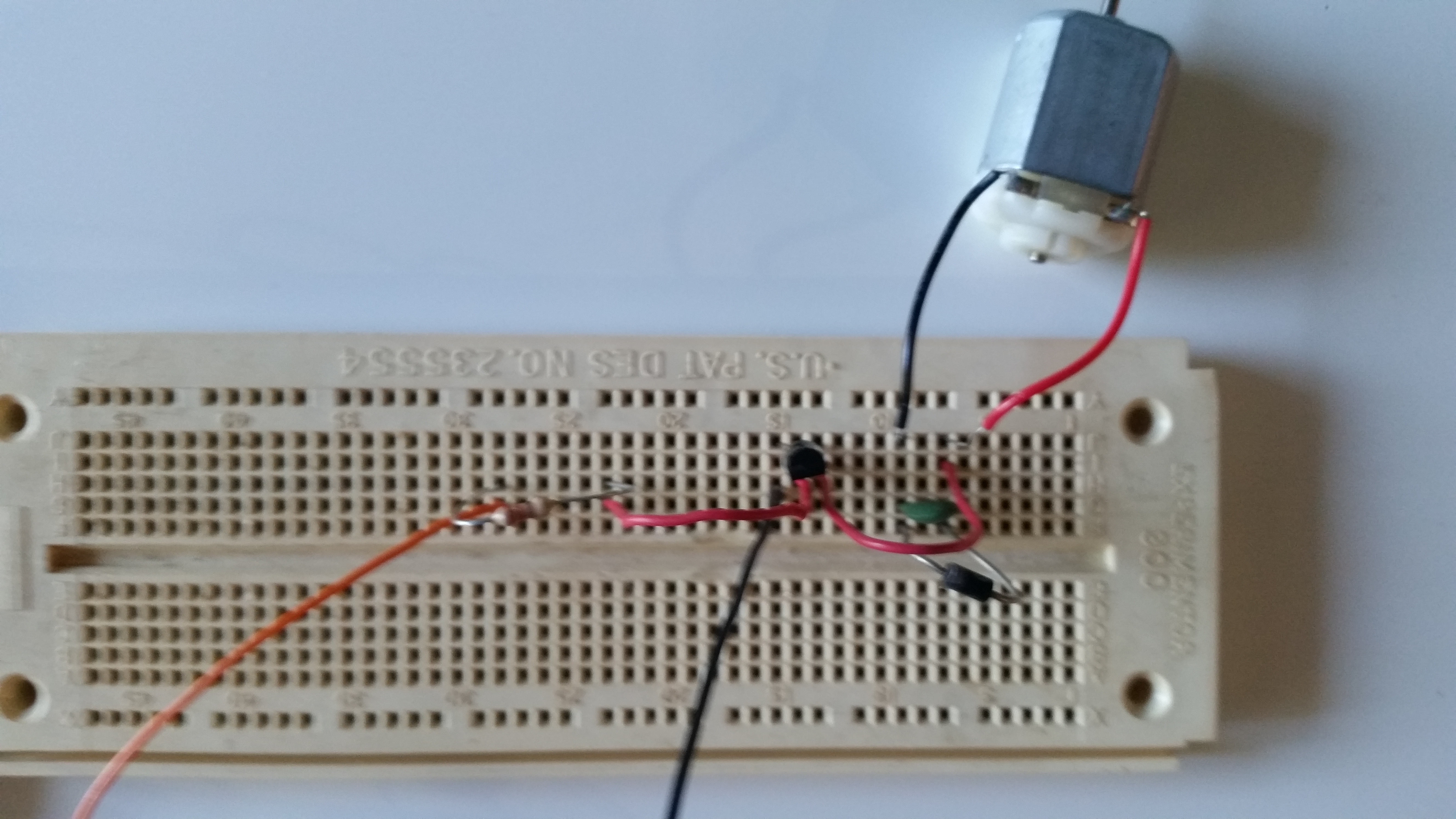
2) Build the simple Motor circuit and wire up a motor or light
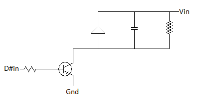
You typically shouldn't wire up a digital output directly to a motor since a motor will probably draw more current than the digital output is rated for.
Instead you should have a small amplifying switch circuit, and a separate power supply to drive the motor.
This can be done with a transistor circuit to amplify any of the digital output signals from Arduino ports.
A diode and capaciter in parallel to the motor prevents problems with the circuit when the motor is stopped and it momentarily acts as a little generator.
This circuit can be used for driving a small motor from just about any digital output like a smartphone parallel port, PC parallel port, etc., not just this project.
Here's a diagram of the circuit you want to wire up.
3) use an Ardunio sketch to control the Arduino ports
Every time a byte or bit is written to the data ports, the data will be latched (saved),
and will remain present until something new is written.
Thus you just need to set a bit high to turn on a device,
wait while you want the device on,
and then set the bit low to turn the device off.
To do this, write a program that sets the bits you want to turn on in a byte or char variable,
and send that byte to the digital port, and call a wait routine.
Once the wait routine is done, clear the bits and write them to the digital port.
The data will be held as long as the program is in the wait routine.
Advanced: 4) Build a bi-directional Motor circuit and wire up a motor with an L293 / SN754410 half H-bridge driver
You can't wire up a digital output directly to a motor and be able to control the motor in three different states: stopped, forward, reverse.
Instead you will need two digital outputs, one to control direction and one to turn the motor on and off.
You then need a circuit called an H-bridge in order to be able to switch the current direction to the motor.
This could be built from scratch with transistors, but it's such a popular circuit you can get ICs that have H-bridge or half H-bridge circuits.
The L298 is a popular dual packaged full H-bridge IC, while the L293 (aka SN754410) is a popular quadruple package half H-bridge IC.
You can use two half H-bridge circuits with a little other circuitry to form the equivalent of a full H-bridge so these two ICs offer similar capabilities.
For this example we use an
L293
since it's easier to put this chip into a solderless breadboard.
By using a digital inverter such as a
74LS04,
we can tie two half H-bridges driver inputs together so that one always has the opposite state as the other.
Here's a diagram of the circuit you want to wire up.
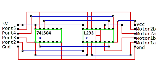
Note that in an h-bridge circuit there is a separate voltage supply for the motors vs. for the digital logic,
similar to the simple motor circuit described above.
With an Arduino, the digital logic voltage can be provided by the Arduino board.
The motor voltage can be supplied independently and can be different than the 5V supplied for the digital logic.
Also note that with this circuit you will not need the simple motor circuit described above.
Now you need to write a program that sets both a direction bit and a bit to turn on or off the motor,
and call a wait routine.
The data will be held indefinately, but the program will not advance as long as the it is in the wait routine.
Once the wait routine is done, clear the bits and write them to the digital port to turn the motors off before turning them on in a different direction.
Here's an example of the Arduino Sketch C code that, with the above circuit, can be used to drive a rover with tank drive.
It should be able to drive the rover forward, then reverse, and then turn before repeating.
const int motorPin4 = 4;
const int motorPin5 = 5;
const int motorPin6 = 6;
const int motorPin7 = 7;
const int nTimePerDistance = 1; // ToDo: implement
const int nTimePerAngle = 1; // ToDo: implement
// stopped
void Stop()
{
digitalWrite(motorPin4, LOW);
digitalWrite(motorPin5, LOW);
digitalWrite(motorPin6, LOW);
digitalWrite(motorPin7, LOW);
delay(1000);
}
extern void setup()
{
pinMode(motorPin4, OUTPUT);
pinMode(motorPin5, OUTPUT);
pinMode(motorPin6, OUTPUT);
pinMode(motorPin7, OUTPUT);
Stop();
}
// forward
void Forward(int nDistance)
{
digitalWrite(motorPin4, HIGH);
digitalWrite(motorPin5, HIGH);
digitalWrite(motorPin6, HIGH);
digitalWrite(motorPin7, HIGH);
delay(nDistance * nTimePerDistance);
}
// reverse
void Reverse(int nDistance)
{
digitalWrite(motorPin4, HIGH);
digitalWrite(motorPin5, LOW);
digitalWrite(motorPin6, HIGH);
digitalWrite(motorPin7, LOW);
delay(nDistance * nTimePerDistance);
}
// forward on one side and reverse on the other
// results in turning
void TurnRight()
{
digitalWrite(motorPin4, HIGH);
digitalWrite(motorPin5, HIGH);
digitalWrite(motorPin6, HIGH);
digitalWrite(motorPin7, LOW);
delay(5000);
}
extern void loop()
{
Forward(5000);
Stop();
Reverse(5000);
Stop();
TurnRight();
Stop();
}
Here's a video of a
Arduino (AVR) controlled Snap Rover robot
using this h-bridge circuit and this code.
Here's links to tools that are needed or might be helpful when programming an AVR chip on an Arduino board:
Here are some architecture characteristics that can be demonstrated by these two control solutions.
These differences can be used for teaching processor and microcontroller concepts.
control solutions
| Z80 custom with KIOS |
AVR Arduino |
|
CISC
|
RISC
|
|
von Neumann architecture
|
Harvard architectures
|
|
Run-time software abstraction layer
|
Compile time coding abstraction macros
|
|
custom electonics board
|
pre built Arduino board
|
|
|
|
Copyright (C) 2019 - 2025 R. J. Kuhn.
Please note that you are not allowed to reproduce or rehost this page without written permission.